Introduction

prereq only Loudspeaker /Daughterboard

  1. T6N11x3XZEYKAQGD
    • Before you begin, switch off your phone.

    • Apply a heated iOpener to the back of the phone to loosen the adhesive beneath the back cover. Apply the iOpener for at least two minutes.

  2. luJPtrYN4Q6HMMFP
    luJPtrYN4Q6HMMFP
    vfKwpnaLSf4XXLxc
    euP4HBY3dbJAt3eE
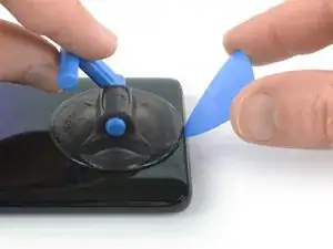
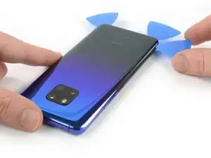
    • Secure a suction handle to the bottom of the back cover, as close to the edge as possible.

    • If the phone's rear glass is cracked, the suction handle may not stick. Try lifting it with strong tape, or superglue the suction handle in place and allow it to cure so you can proceed.

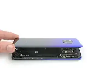
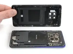
    • Lift the back cover with the suction handle to create a small gap between the cover and the frame.

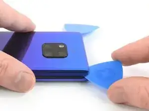
    • Insert an opening pick into the gap.

    • If you have trouble, apply more heat to further soften the adhesive. Follow the iOpener instructions to avoid overheating.

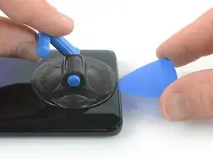
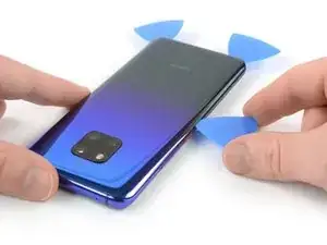
    • Slide the opening pick to the bottom right corner.

  3. 5Z4QhiVvV1vZTtrE
    5Z4QhiVvV1vZTtrE
    uZAfoeGGUGOxCddm
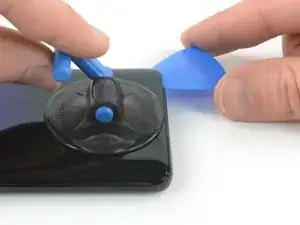
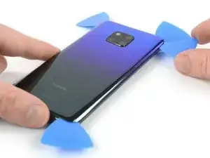
    • Insert a second opening pick and slide it to the bottom left corner to cut the adhesive.

    • Leave the opening picks in place to prevent the adhesive from resealing.

  4. 2dSLfHBrGIFttkGs
    2dSLfHBrGIFttkGs
    DoLrVQmGbuZJULNg
    Eypx2rSPbcMjGCwr
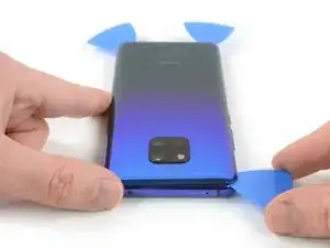
    • Insert a third opening pick at the bottom left corner.

    • Slide the tip of the opening pick from the bottom left corner along the side of the phone to cut the adhesive.

    • Leave the opening pick in its place at the top left corner to prevent the adhesive from resealing.

  5. 6WnBtZMK43wxHveR
    6WnBtZMK43wxHveR
    GQBQ1HWZEka4lFsK
    • If the adhesive becomes hard to cut, it has most likely cooled down. Use your iOpener to reheat it.

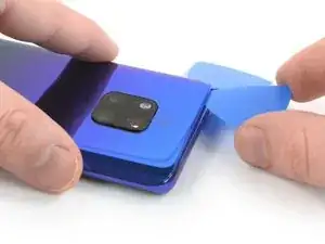
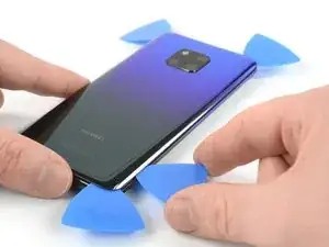
    • Insert a fourth opening pick under the top left corner of the back cover.

    • Slide the opening pick along the top edge of the phone to cut the adhesive.

    • Leave the opening pick in the top right corner to prevent the adhesive from resealing.

  6. NovKITwk3UL2feX3
    NovKITwk3UL2feX3
    BuSQUCYmgB2JeTcM
    • Insert a fifth opening pick at the top right corner of the phone.

    • Slide the opening pick along the right side to cut the remaining adhesive.

  7. 4JrOvDgRWKWBZJlI
    4JrOvDgRWKWBZJlI
    GLIRunMQdDKARIPG
    • Lift and remove the back cover.

    • Before installing fresh adhesive and reassembling, remove any remaining adhesive from the phone, and clean the glued areas with isopropyl alcohol and a lint-free cloth.

    • During reassembly, this is a good point to power on your phone and test all functions before sealing it up. Be sure to power your phone back down completely before you continue working.

    • Secure the new back cover with pre-cut adhesive or double-sided adhesive tape. After installing the rear glass, apply pressure for several minutes to help the adhesive form a good bond, such as by placing it under a stack of heavy books.

  8. QTJWpFmcAgTT5n11
    • Remove the eight Phillips #00 screws (4.3 mm length).

    Hallo, es sind nur 7 Kreuzschlitzschrauben à 4.3mm. Eine (die zweite von unten links nach rechts) ist massiv kürzer und silbern.Gruss Jörg

    Jörg Schircks -

  9. MiSGOjF1ElieXB4f
    MiSGOjF1ElieXB4f
    oFHbiNprUrLkwvNC
    KwaBLTg5RXP4kfky
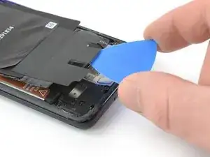
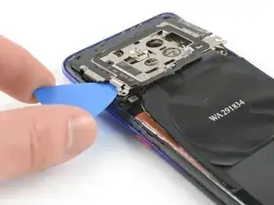
    • Slide an opening pick under the black adhesive at the bottom left of the charging coil.

    • Carefully slide the opening from the left to the right side to loosen the adhesive.

  10. qFwGZl6tWxFSdmpv
    qFwGZl6tWxFSdmpv
    RM4csYJiJmTurDRa
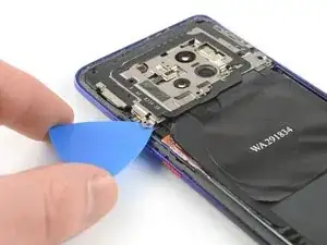
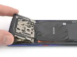
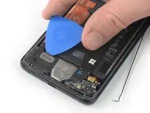
    • Insert an opening pick under the bottom left corner of the motherboard cover.

    • Use the opening pick to pry up the motherboard cover.

    • Do not try to remove the motherboard cover all the way yet. The flex cable of the flash assembly is still connected to the motherboard.

  11. okUqcHqwhWfBahYW
    okUqcHqwhWfBahYW
    Zc4I26gDpQFWBn2e
    • Carefully fold the motherboard cover in the direction of the battery.

    • Take special care to avoid ripping the flash assembly flex cable as it is still connected to the motherboard.

  12. SsCjvRCfnu6xglQM
    SsCjvRCfnu6xglQM
    EeERFWrAg4543I3X
    XCOyRiTQrKjpsgDf
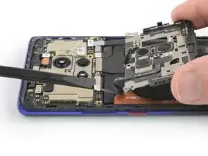
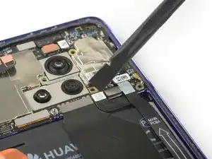
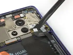
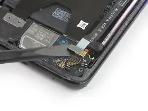
    • Use a spudger to pry up and disconnect the flash assembly flex cable.

    • When you disconnect connectors like these, be careful not to dislodge the small surface-mounted components surrounding the socket.

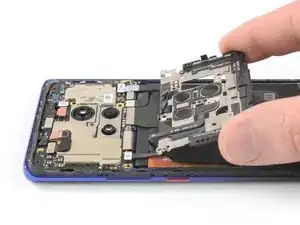
    • Remove the motherboard cover including the NFC and charging coil.

  13. 5YIKPjRIpDio4bAY
    5YIKPjRIpDio4bAY
    mqAqVUbRoPW3gCm3
    • Use a spudger to pry up and disconnect the battery connector.

  14. HAjP5MCuK5fsdK6T
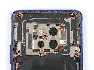
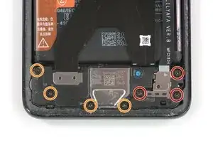
    • Remove the three Phillips #00 screws (4.3 mm length).

    • If you want to remove or replace the loudspeaker, daughterboard, battery, or the OLED screen, remove the four Phillips #00 screws (4.3 mm length) which hold down the loudspeaker assembly.

  15. 6lmtwXDUNI4ncDsk
    6lmtwXDUNI4ncDsk
    BJyiU4NbepGM6gcX
    VE6A6nDE6VLFol2y
    • Slide an opening pick under the top right corner of the daughterboard cover.

    • Use the opening pick to pry up the daughterboard cover. Remove the daughterboard cover with tweezers.

  16. UgFiK4evMPvDDmfW
    UgFiK4evMPvDDmfW
    sBZcmSdbCJdUxOWv
    • Use a Spudger to pry up and disconnect the interconnect flex cable from the daughterboard.

  17. ZnaGO1bJWZ5PZFni
    ZnaGO1bJWZ5PZFni
    e5wMFaUZKnYt6ocN
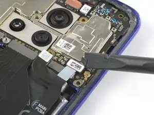
    • Use a Spudger to pry up and disconnect the interconnect flex cable from the motherboard.

    • Remove the interconnect flex cable.

  18. MQN2t14UeWCHSgne
    MQN2t14UeWCHSgne
    cjIcpMcOHcr3OedT
    • Use a pair of tweezers to pry up and disconnect the connector of the black coax cable from the daughterboard.

    • Unroute the black coax cable from the metal clip on the daughterboard and fold it to the side.

  19. rljWK1ARpFllhHkH
    rljWK1ARpFllhHkH
    DLHIPcuMMuhYbW1U
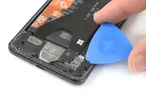
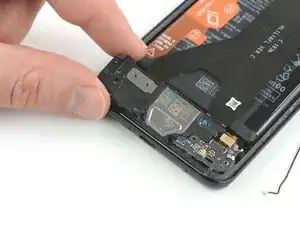
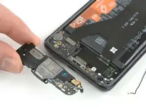
    • Slide an opening underneath the top left corner of the loudspeaker cover.

    • Use the opening pick to pry up the loudspeaker and daughterboard assembly.

    This part is difficult to remove, does not come out easily.

    Hugues Laliberte -

    Turns out that you have to remove the 4 orange screws of step 14.

    Not sure why there is a IF statement on this step.

    Hugues Laliberte -

  20. SXDKmseTJEpLSS6s
    SXDKmseTJEpLSS6s
    nLhRS1PEYrsKeNO2
    • Remove the loudspeaker and daughterboard assembly.

Conclusion

To reassemble your device, follow these instructions in reverse order.

Dominik Schnabelrauch

Member since: 23/11/16

224668 Reputation

0 comments