Introduction

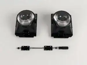
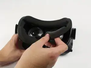
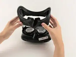
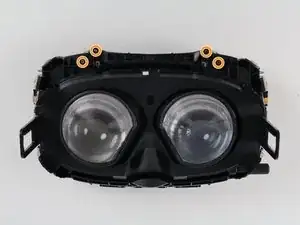
This guide will show you how to replace the HTC Vive's individual lens and OLED assemblies. Each assembly includes the lenses, lens housing, and OLED screen.

  1. eET2TXVDGYKeXa4F
    eET2TXVDGYKeXa4F
    V3ElVYy2VtleANYO
    nU4wdXNBMJKyM3Dc
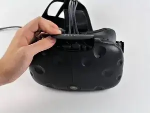
    • Slide the HTC panel covering the cables forward, away from the Vive.

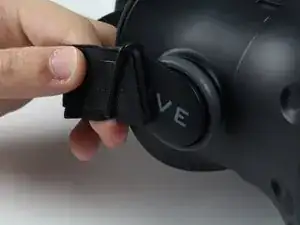
    • Gently pull on each of the four connectors to remove the sound and Three-in-One cables.

  2. ZfwAllhJIABUYQWS
    • Undo the hook and loop tape on the straps.

    • Slide the ends of the straps through the hinge loops.

  3. qy5D6r6rbEhGgFFC
    • Pull the facerest cushion off away from the Vive, separating the hook and loop tape.

  4. CVEiKaUHdNU5mDHu
    CVEiKaUHdNU5mDHu
    Jogt4PrUsinxiSTF
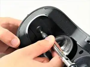
    • Use a T6 Torx Screwdriver to remove either of the two 12mm hinge screws holding the two hinges in place.

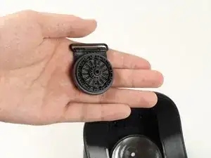
    • Allow the hinge to fall away once the screw is removed.

    • Repeat for the opposite side.

  5. QnN4GHvuyRZDtPHF
    QnN4GHvuyRZDtPHF
    3qkXVNvoLx65LiqC
    dDdMpBJDsbldSJZJ
    • Slide the plastic facerest away from the device.

  6. ArbHQYV6uXSmhBui
    ArbHQYV6uXSmhBui
    KcpZNb2yhEixgAUP
    bRk4B14QkE1dVCmc
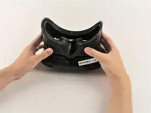
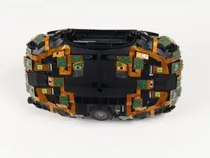
    • Orient the Vive so that the camera is facing towards you and the connector ports are facing upwards.

    • There are four screws you need to remove that are covered with small black stickers (two on top, two on bottom).

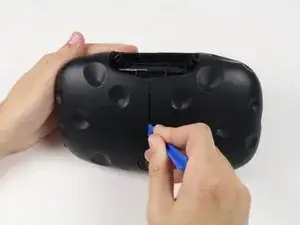
    • Use a plastic opening tool to gently pry up the left side of the outer sheath.

    • If the left sheath is glued down, slide your plastic opening tool along the middle seam to break the bond.

    • Slide the left side of the sheath outwards.

  7. mufy1FE3Oy6OiPjp
    mufy1FE3Oy6OiPjp
    NZWGfxXFRIvg2xsa
    3FEbJDAGLOR6pkWm
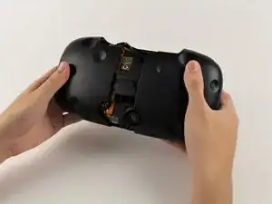
    • Slide a plastic opening tool underneath the right side of the sheath to remove any remaining glue.

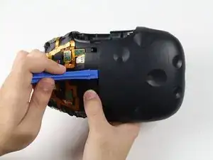
    • Using the plastic opening tool, pry the right side of the sheath upwards slightly.

    • Using your hands, slide the right side of the sheath outwards.

  8. ClbfRgFigW421DYM
    ClbfRgFigW421DYM
    CKNOdyrrHF4Cmmf2
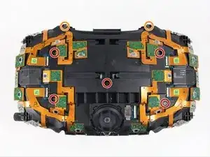
    • Remove the five 4mm Philips #00 screws holding the sensor array to the motherboard.

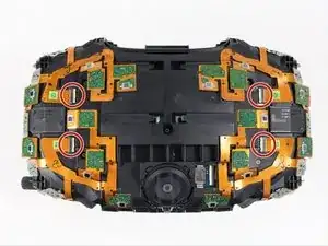
    • Remove the two 4mm Philips #00 screws holding the sensor array to the midframe.

  9. QhjmsRqvrB5s2MbK
    QhjmsRqvrB5s2MbK
    WnKmD4WMlAWDrxEy
    • Using a pair of ESD safe tweezers, gently pull the four ribbon cables out horizontally from the sensor array.

  10. GpoTpgAbQ6ZKNccl
    GpoTpgAbQ6ZKNccl
    eSm3ZDZYRJTD6EZD
    VEoE5nJGOhygE2do
    • Be careful not to lift the sensor array too far from the rest of the device because the camera ribbon cable may tear.

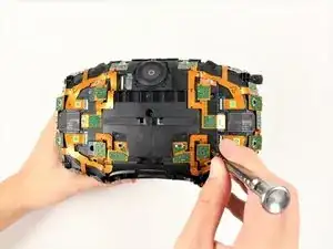
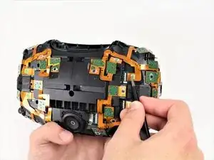
    • Lift the sensor array away from the rest of the Vive until the camera cable tugs back and hold it in place.

    • The camera ribbon cable must be pulled out of its socket vertically, as opposed to all other ribbon cables which slide out horizontally.

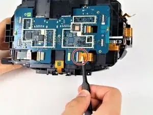
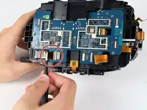
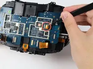
    • Disconnect the camera by lifting its ribbon cable up and away from the motherboard using a pair of ESD safe tweezers.

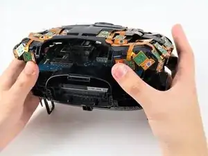
    • Lift the sensor array upwards away from the motherboard to separate the array from the device fully.

  11. GXfxyfV6oDwAYVJj
    GXfxyfV6oDwAYVJj
    h3gPNK4nGTey2ubX
    15gpJBG43N1Sd6NR
    • Loosen the three ribbon cables that are attached to the motherboard by grabbing the tabs on the side of the ribbon cables' connectors and pulling gently outwards.

    • Fully detach the same three ribbon cables by grabbing each cable with tweezers and sliding them outwards horizontally.

  12. 1fSEv4EKgR5awQQr
    1fSEv4EKgR5awQQr
    dR3TtBgFwHcKKMTS
    • The bottom of the motherboard is secured by two hooks, indicated in the first photo. Do not pull the motherboard directly outwards, as doing so can cause damage.

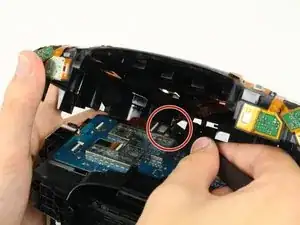
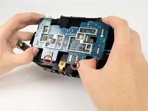
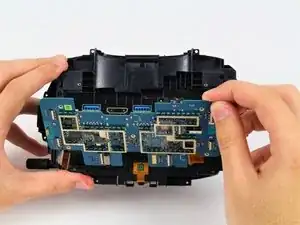
    • Pivot the top of the motherboard outwards until it has cleared the top of the plastic housing.

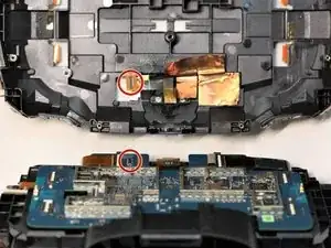
    • Pull the motherboard up and away from the plastic housing, away from the two hooks.

  13. YNATOghlfXBCAurq
    YNATOghlfXBCAurq
    u1XKEU4UBvSMSZtL
    • Grab the tabs on the side of the ribbon cable's connector and pull gently outwards to loosen it.

    • Remove the ribbon cable for the power button by grabbing the cable with tweezers and sliding it outwards horizontally.

    • The ribbon cable for the power button is located on the side of the device opposite from the focus knob.

  14. DEbZPnCWhNVKhkqh
    DEbZPnCWhNVKhkqh
    JDYVDVPjGNGawnTi
    ARqrggfuuFoNdIYJ
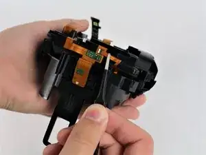
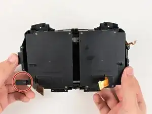
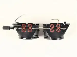
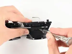
    • Remove the four 4mm #00 Philips screws by the nose rest holding the midframe to the eyepiece assembly.

    • Remove the four 4mm #00 Philips screws on the top of the device, directly across from the four by the nose.

  15. JYLj52163tOKCOdy
    JYLj52163tOKCOdy
    iaX4NcqHwEuOAJOn
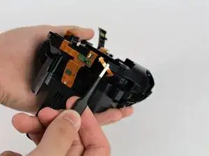
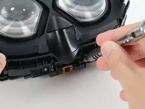
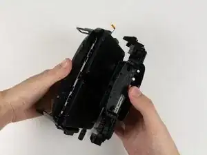
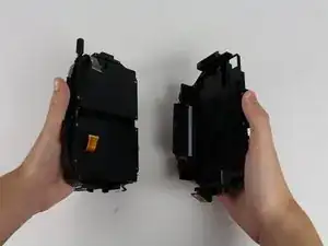
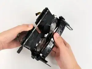
    • With one hand on the midframe and the other on the eyepiece assembly, pull the two parts away from each other.

  16. LkFRTnDRFThClNPU
    LkFRTnDRFThClNPU
    LJmxI1YriteAFITn
    X2wAASIYktIOMJMw
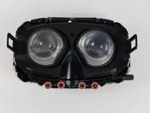
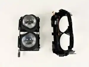
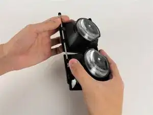
    • Pivot the bottom rod attached to the eyepieces outwards from the facerest to free the eyepieces.

    • The bottom rod is the rod that the focus knob is attached to.

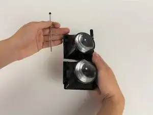
    • Pull facerest from the eyepieces to separate the parts.

  17. hkqMnGTFkZrYPTGk
    • Pull off the rubber liner between both eyepieces.

  18. CRFyNAh5vYmrygIR
    CRFyNAh5vYmrygIR
    VxOjTcBHYvFCOhGq
    SsojsiZmfq5NQFLE
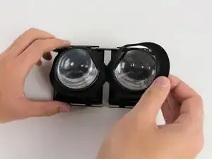
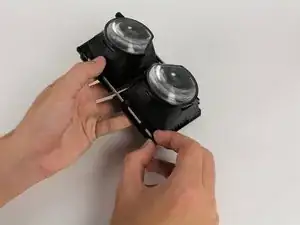
    • Pull one of the rubber ends off the top rod.

    • The top rod is the rod that does not have the focus knob attached to it.

    • Pulling from the other end of the rod, slide the top rod out.

  19. wALriTdlor2N6HOh
    wALriTdlor2N6HOh
    IKVCP5RwXE6p4FYv
    rFqIkbL6QfYvt4Ml
    • Remove the four 3mm #00 Philips screws from each eyepiece, removing eight screws total.

    • The eyepieces will detach from the bottom rod once the screws are removed.

Conclusion

To reassemble your device, follow these instructions in reverse order.

Caleb Watts

Member since: 25/09/17

2427 Reputation

0 comments