Introduction
The HTC Vive's lenses can become scratched, cracked, or dirty with use. This guide will show you how to replace one or both of the HTC Vive lenses.
-
-
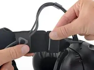
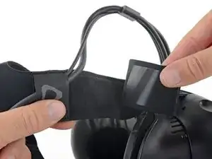
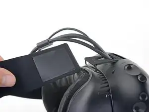
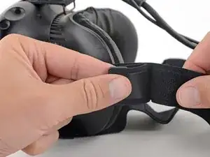
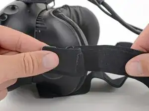
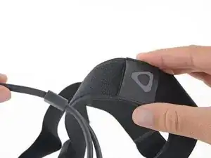
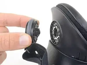
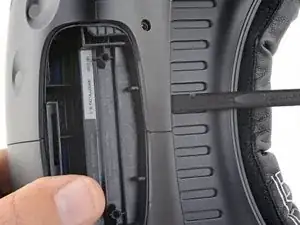
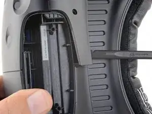
Pull the hook-and-loop (Velcro) closure at the top of the head strap apart to release the top of the head strap.
-
-
-
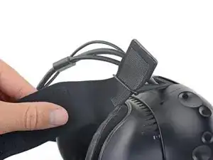
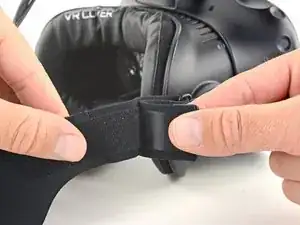
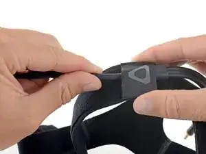
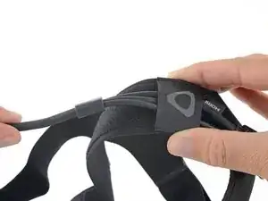
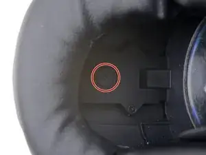
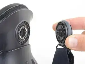
Pull the hook-and-loop closure at the right side of the head strap apart to release the right side of the head strap.
-
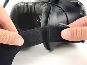
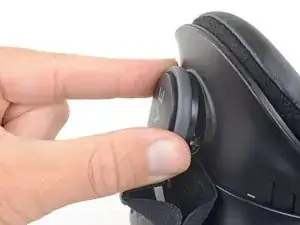
Slide the right side of the head strap through its metal loop to remove it.
-
-
-
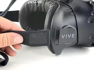
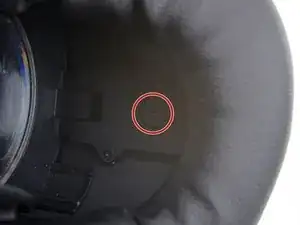
Pull the hook-and-loop closure at the left side of the head strap apart to release the left side of the head strap.
-
Slide the left side of the head strap through its metal loop to remove it.
-
-
-
Slide the head strap along the cable, away from the Vive.
-
When the head strap comes to the end of the cable, gently slide it over the plugs and remove it.
-
-
-
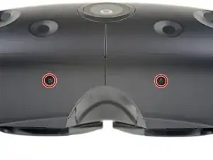
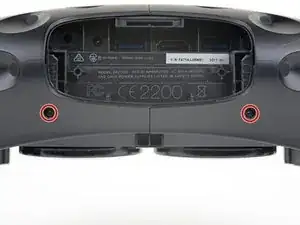
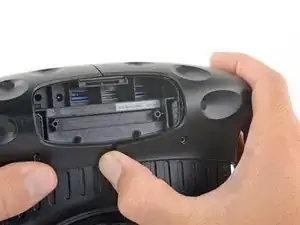
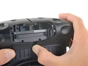
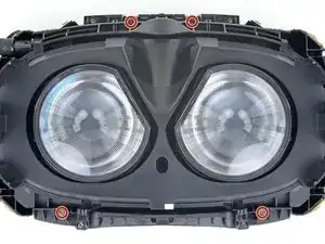
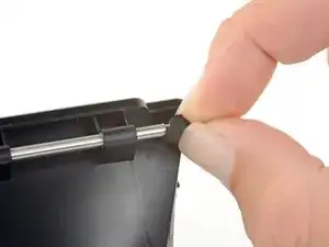
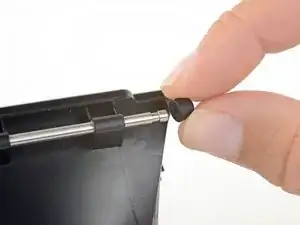
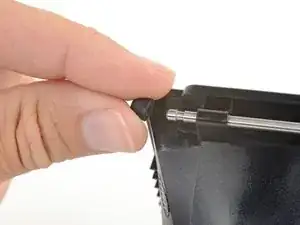
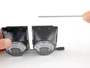
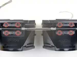
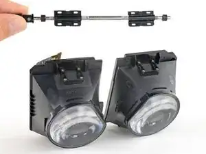
Use a T5 Torx driver to remove the two 12 mm-long screws securing the head strap mounts on either side of the headset.
-
-
-
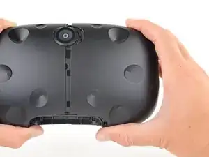
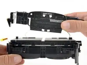
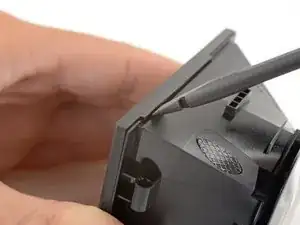
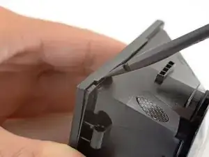
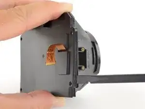
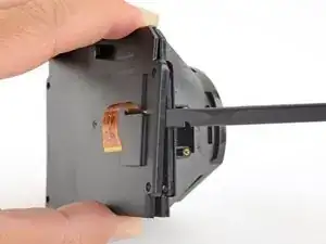
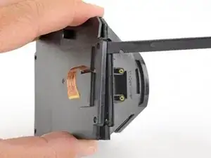
Use the flat end of a spudger to pry up the top edge of the right half of the outer shell, behind the component cover and near the seam in the center, until it is unclipped from the headset.
-
-
-
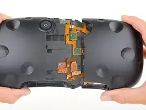
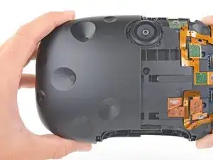
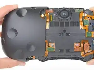
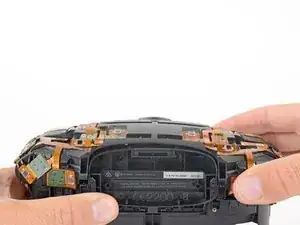
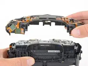
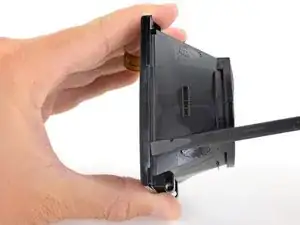
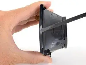
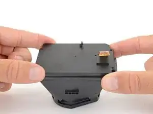
Grasp the right half the outer shell and pull it to the right and toward the front of the headset until you feel the clips on the front of the cover release.
-
If the shell is difficult to remove, try prying along the seam with the flat end of a spudger to release the clips.
-
-
-
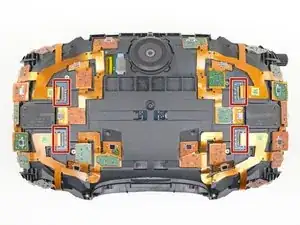
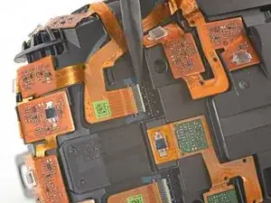
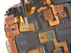
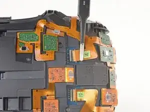
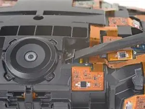
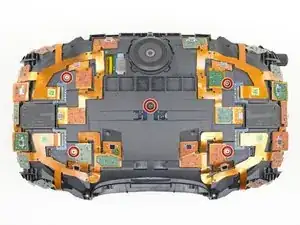
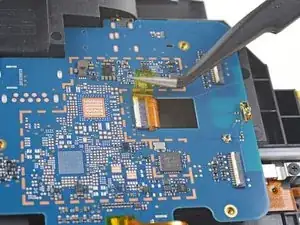
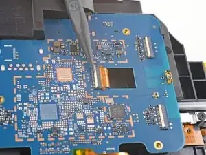
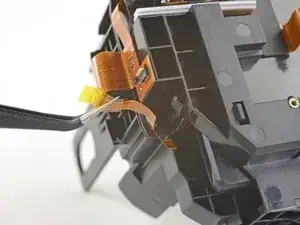
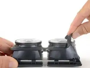
Use the pointed end of a spudger to flip up the small locking flap on one of the sensor array ZIF connectors.
-
Slide the cable straight out of its socket on the motherboard.
-
-
-
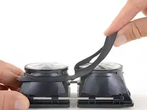
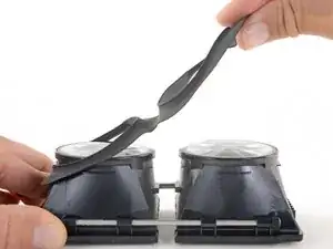
Repeat the previous step for the remaining three sensor array cables to disconnect the remaining cables.
-
-
-
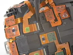
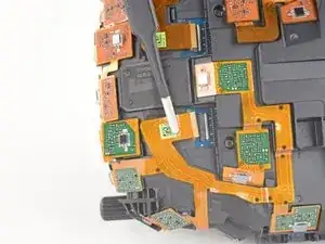
Use the flat end of a spudger to pry the camera cable connector straight up from its socket on the motherboard.
-
-
-
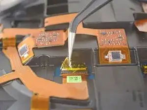
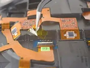
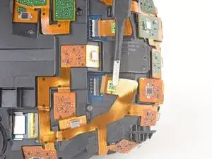
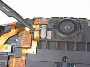
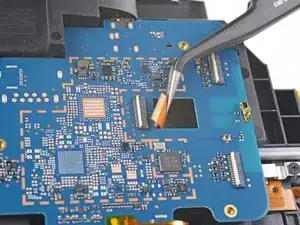
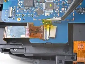
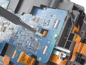
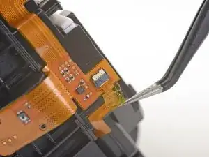
Remove the tape covering the interconnect cable socket.
-
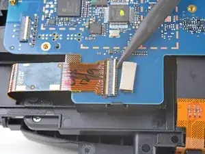
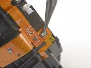
Use the point of a spudger to flip up the small locking flap on the cable socket.
-
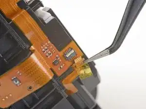
Slide the interconnect cable straight out of its socket on the motherboard.
-
-
-
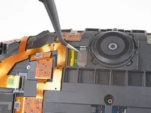
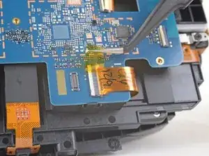
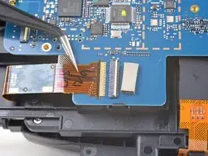
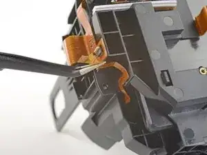
Remove the tape covering the left OLED cable socket.
-
Use the point of a spudger to flip up the small locking flap on the cable socket.
-
Slide the left OLED cable straight out of its socket on the motherboard.
-
-
-
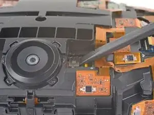
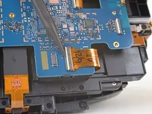
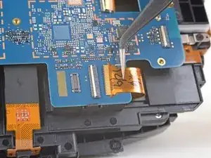
Remove the tape covering the right OLED cable socket.
-
Use the point of a spudger to flip up the small locking flap on the cable socket.
-
Slide the right OLED cable straight out of its socket on the motherboard.
-
-
-
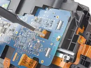
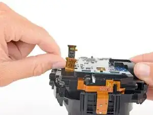
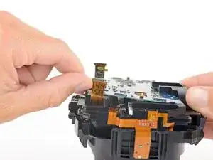
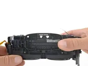
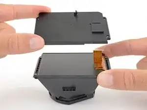
Press the non-port-end of the motherboard toward the top of headset while hinging it away from the midframe to free it from the clips securing that end.
-
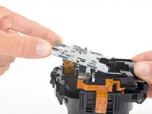
Slide the motherboard toward the bottom of the headset, over the clips, to remove it.
-
-
-
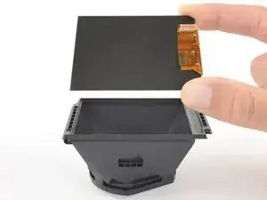
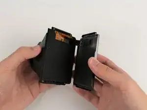
Use the flat end of a spudger push up one edge of the OLED cover and start unclipping that edge.
-
-
-
Very carefully lift the OLED display by its edges out of its frame.
-
Repeat this process for the other OLED display.
-
-
-
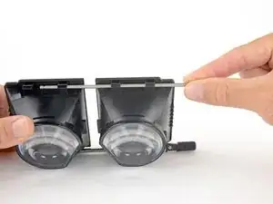
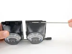
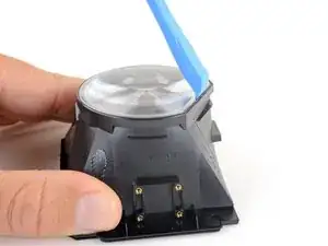
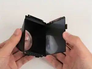
Use an opening tool to pry up the flat edge of the lens.
-
If it's difficult to pry up, apply the iOpener for another 30 seconds to further soften the adhesive.
-
-
-
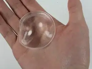
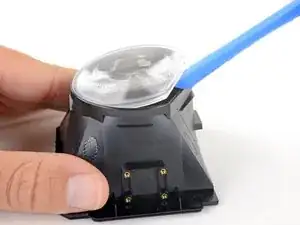
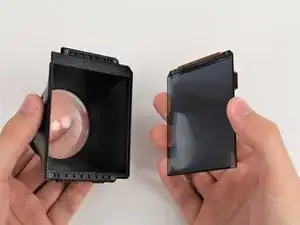
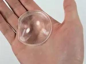
Remove the lens.
-
Repeat the last two steps to remove the other lens.
-
Only the lens and OLED frames remain.
-
-
-
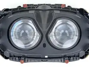
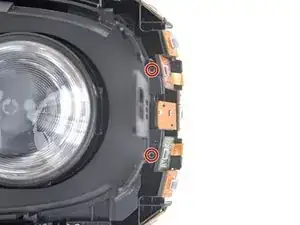
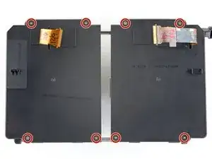
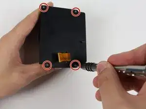
Remove the four 2mm #00 Philips head screws holding the screen in place from the eyepiece assembly.
-
-
-
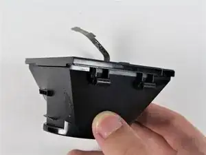
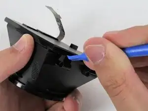
Use a plastic opening tool to gently pry around the seam between the eyepiece housing and the screen.
-
Gently pull the screen cover away from the eyepiece housing, threading the ribbon cable through the hole.
-
-
-
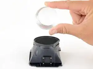
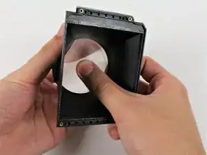
Hold your hand in front of the lens and be ready to catch the lens during its removal.
-
From the inside of the black plastic housing, push gently around the edges of the lens to remove it.
-


To reassemble your device, follow these instructions in reverse order.
9 comments
Or… you can simply use an exacto knife and pry the lenses out without taking the entire HMD apart!
You can insert a scalpel type knife between the lens and the housing and work your way around.
techy76 -
I’ve got to agree . This is the absolute worst way to do what’s essentially a simple operation. So many ways this could go wrong for the user if they’re not careful.
This reeks of click bait re-purposing of the tear-down coverage.
This has to be the most overly complicated approach for a VERY simple fix. Takes about 5 seconds to pop out the lenses by carefully prying at the flat edge with a butter knife, exacto knife, etc.
Agreed! what rubbish…
We are showing you the most technical and professional way to take out the lens. Remember this is just a guide. You can use whichever way you most comfortable to take apart your HTC.
I think the most professional way is the way that puts the device in the least risk. While this is an incredible teardown manual, you have the same risk at the end popping the lens out as you would performing the extraction externally using light heat, a thin pry tool, and some patience. Most pop out on the first try depending on the age of the unit/glue. Being that there is no risk to the damaged lenses you are replacing if that is the reason, there is no reason to put forth such an effort. There is nothing unprofessional about that except the labor charge if providing the service would be less to a customer, which if paid on time would make it not professionally feasible, so charge for the job. This feels like removing the engine from a car to change the oil.
DevDoc -