Introduction

The disassembly of the HTC Vive Cosmos is provided.

Static Warning for circuit board interaction. When dealing with jumper cables and circuit boards touch metal not located on Vive for 15 seconds before removing component.

  1. HUToAMwejjhETdhK
    • Peel back the interchangeable foam velcroed to the headset.

  2. 5tP5g4epWjExN61v
    • Hold the button on the inside of the headset.

    • Pull back the frontplate away from the Vive.

  3. UMJNt1uwxIccSW11
    • Peel the two warranty stickers using a driver.

    • Covers may be peeled back using other tools like a spudger.

  4. bbuiBnKFkkpN4Nxv
    • Unscrew nineteen screws using the T5 Torx driver.

  5. kQVJ2SKCSZpPiisP
    kQVJ2SKCSZpPiisP
    tOiRYoRtacyoIMAd
    • Remove the covers beneath the warranty stickers.

  6. 5iQbInWrBjxmLJM4
    • Insert card between plate and camera plate to separate and remove.

    • May use card or other soft flat surfaces like a spudger.

  7. ZhBJPKpNn1IEnryh
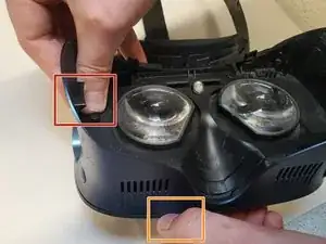
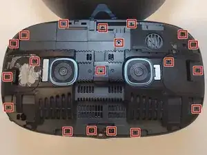
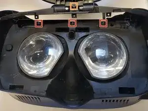
    • Unscrew the three torx screws using the T5 X 50 mm screwdriver.

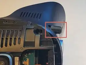
    • Unscrew the one Philips screw using the 10 mm screwdriver.

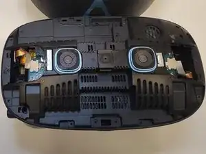
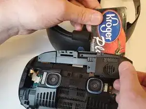
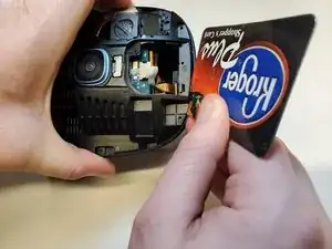
    • Detach headband from headset.

  8. fmljtPDScdYlaEYY
    • Insert card between camera plate and the headset to separate.

    • May use card or other soft flat surfaces like a spudger.

  9. CVS3tyFZHRL6qxCe
    • Slide the focus knob out of the plastic holding and off the focus rod.

  10. qBWQLZPgX6K5S6Vl
    qBWQLZPgX6K5S6Vl
    MidPuT4Rr5Jmptbq
    • Static Warning for circuit board interaction. When dealing with jumper cables and circuit boards touch metal not located on Vive for 15 seconds before removing component. Keep in mind for remaining steps.

    • Unplug the jumper cables from the circuit boards to detach.

  11. qTLVZRciqx2hprfT
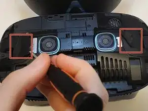
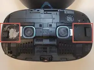
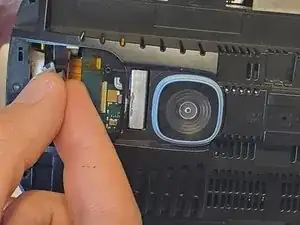
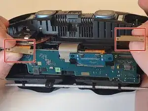
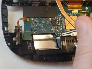
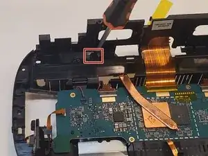
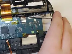
    • Unscrew the four silver Torx screws on the jumper cables using the T5 driver.

    • Keep note of the silver Torx screws which are different than the other screws.

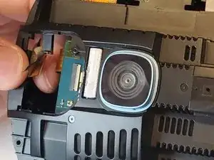
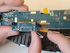
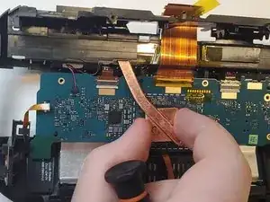
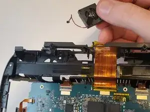
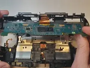
    • Pull the jumper cables away from the holding and remove.

  12. cDbOEwcRuFdxVGZD
    • Unscrew the nine Torx screws using the T5 driver on the circuit board.

  13. wAgu4rfrhMBQijwB
    • Remove the jumper cables to fully release the cable port board.

  14. GwaC4V5ROfZDtQwv
    • Unscrew the six Torx Screws on the camera board with the T5 driver.

  15. nfjVqIxwf5MGfjxT
    • Unscrew the one Torx Screw using the T5 driver.

  16. bOxKhXRTpTl2ZkAe
    • Pull and maneuver the heat duct out of the holding.

    • Exercise caution to carefully remove component.

    • The thermal paste may scratch off in the process but that is okay.

  17. lqfOiQCebXre1Atf
    lqfOiQCebXre1Atf
    FRq3FrBbqrQrWoZZ
    • Unplug the fan from the camera board.

  18. XPMSFnKEqrwTXotp
    • Insert screwdriver beneath strip plug to remove.

    • May use another tool that is able to fit beneath strip plug and gently remove.

  19. C1UDaNfRjvBlLU4i
    • Lift camera board and remove.

Conclusion

To reassemble your device, follow these instructions in reverse order.

Jalyssa Smith

Member since: 11/04/23

289 Reputation

One comment

Thanks for not mentioning the microphone and the fact that you also tore yours doing the disassembly! Will you replace the mic that was working before i took it apart to repair other issues? No? Exactly. Don't do any more guides and people: find a better one. Moron.

Lee Ball -