Introduction

This guide shows how to replace the built-in laptop speakers. This repair will fix many issues for the laptop speakers such as, low sound quality, no sound, crackling sound, etc.

  1. 4yvaucKRSXInk3Sa
    4yvaucKRSXInk3Sa
    TLKh6tt6cMpvaiiM
    jDT1gqwY6XofatJe
    • Before you begin to remove the bottom cover, shut down the computer. Disconnect all external devices and unplug the AC adapter. Flip the laptop upside down.

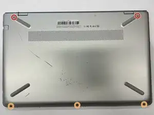
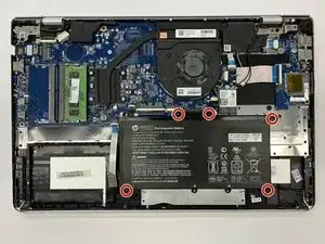
    • Use a Phillips #0 screwdriver to remove five screws from the bottom cover:

    • Two 5.6 mm screws

    • Each of these screws are beneath the two rubber feet on the rear side of the laptop (near the display hinges). You do not have to completely remove the rubber feet to remove the screws; simply peel the top of the feet to reveal the screws.

    • Three 5.8 mm screws

    • Throughout this repair, keep track of each screw size and location to avoid damaging your device.

  2. XbeTtMHNvv3o3uCJ
    XbeTtMHNvv3o3uCJ
    AYYgvF3IQDg5SFNt
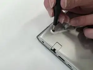
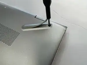
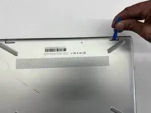
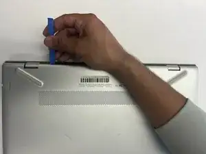
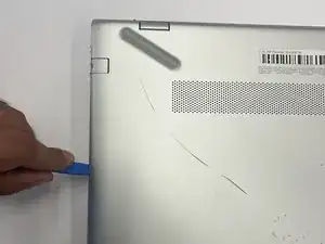
    • Insert an opening tool into the space between the display hinges and the bottom cover.

    • Firmly push the opening tool upwards to separate the bottom cover from these areas.

  3. xqFL4TCmPPnKUnx1
    xqFL4TCmPPnKUnx1
    XdQpyDdQVJ1gABt5
    5UbQlsGJuGRsVxVJ
    • Insert your opening tool and firmly push the tool upwards along the rear edge.

  4. U5dhsJTvBFxChIAE
    U5dhsJTvBFxChIAE
    YTBFoccrj4Z2q2Dv
    mqrlVeLFqK2Umy6m
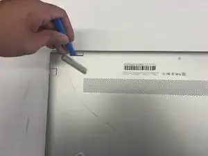
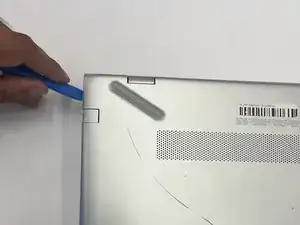
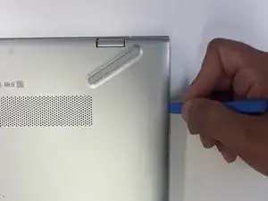
    • Use the opening tool again on the left and right sides.

    • Start prying at the areas closer to the rear of the laptop (near the display hinges) before moving towards areas that are closer to the front of the laptop (away from the display hinges).

    • Pry a little bit on the left side, then pry a little bit on the right side before prying more on the left side again. Working on both sides in this incremental fashion is easier than completely prying one side before starting the other side.

  5. rkRZpjcpDxkx5q2i
    • Lift the bottom cover upwards to remove it.

  6. JwtxM4HTUrTTlNnI
    • Use a Phillips #0 screwdriver to remove the five 5.7 mm screws that secure the battery.

  7. 4LxJpQjRLMYHW1EN
    4LxJpQjRLMYHW1EN
    ODtEt4ruXlLnqRAO
    igQxTvUhLbofUrd3
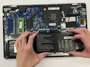
    • Pull the battery towards the front edge of the laptop to disconnect it from the 8-pin battery connector.

    • Lift the disconnected battery upwards to remove it.

    • Calibrate a newly-installed battery to help your laptop get an accurate battery percentage reading.

  8. SbsKr4cfcpYC6ngX
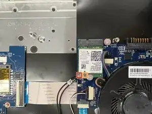
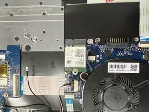
    • Disconnect the WLAN antenna cables from the terminals on the WLAN module:

    • Cable labeled "1/AUX" which connects to the "Aux" terminal

    • Cable labeled "2/MAIN" which connects to the "Main" terminal

  9. OmrFiM3jcP3vaD1d
    OmrFiM3jcP3vaD1d
    vGaasvyvFbcRFCB4
    • Use a Phillips #0 screwdriver to remove the 3.0 mm screw that secures the WLAN module.

    • Removing this screw will cause the WLAN module to tilt up.

  10. LaaYHFGBgUoyAvMk
    • Pull the WLAN module away from the slot at the angle it rises from.

    • Line up the notches on a new memory module with the slot. These notches are designed to prevent incorrect insertion.

  11. rPGUmNDGHSvQGJW4
    • Disconnect the fan cable from the motherboard.

    • Handle the cable by the connector. Avoid pulling on the cables themselves to avoid damaging the cables.

  12. Ww61HlcaJRQPWHR3
    • Use a Phillips #0 screwdriver to remove the three 5.8 mm screws that secure the fan.

  13. DtEvPasOJODhyL1s
    • Lift the fan upwards to remove it.

  14. BTxiCaBDjAoV6WeJ
    • Use a Phillips #0 screwdriver to remove the four 3.0 mm screws that secure the heat sink.

  15. UUZly6VNdT5nPTRx
    UUZly6VNdT5nPTRx
    GoXBJd6WX6poPdvH
    Yy4IipcxhUKJmUVA
    • Lift the heat sink upwards to remove it.

    • Thermal paste must be thoroughly cleaned from the surfaces of both the heat sink and the processor each time the heat sink is removed. Apply new thermal paste before reinstalling the heat sink.

  16. qsRBFCnAIDNqfOBE
    qsRBFCnAIDNqfOBE
    RGKHp51ipbjXbmcu
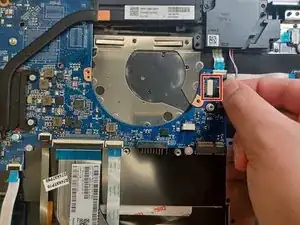
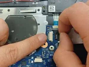
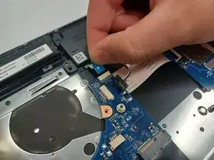
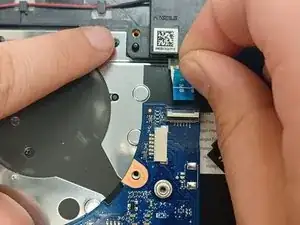
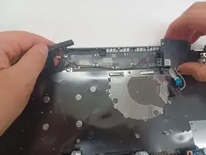
    • Remove the bundled cable connector from the terminal by pulling it horizontally out of its socket.

  17. VIkHUYOICFMTMrTZ
    VIkHUYOICFMTMrTZ
    LAkvDBpnQ1lCVNpQ
    • Remove the ZIF ribbon cable by pulling it gently.

  18. 1tZbAUruxXjlPJt5
    • Use a Phillips #0 screwdriver to remove the 5.8 mm screw on the right speaker.

  19. Gw4YnsZQpBqaA6Pb
    Gw4YnsZQpBqaA6Pb
    dTrVOX1Do5EjmCbS
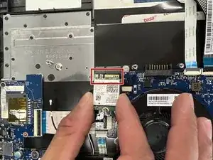
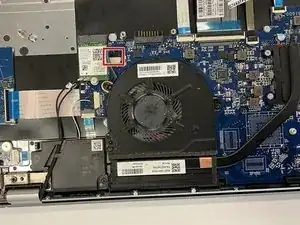
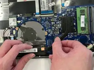
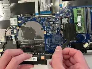
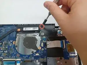
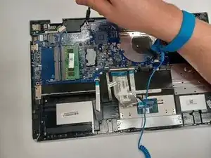
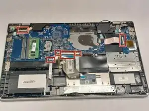
    • Remove 3 silver 2.95 mm screws with a Phillips #0 screwdriver

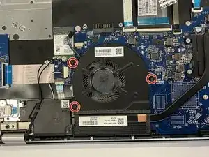
    • Remove the 4 black 5.65 mm screws with a Phillips #0 screwdriver.

  20. K1GKpPljTQEKpfCL
    • Remove the power supply female connector by lifting it up via the black stick spudger.

  21. hUeIFpqlqNe1bGAv
    hUeIFpqlqNe1bGAv
    MYlN5yJJxGbEfn4j
    2UJc3IdRexJqgIEt
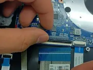
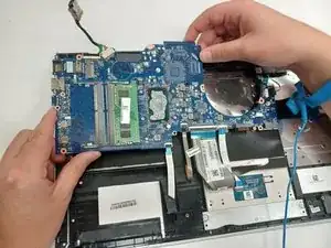
    • To remove the ZIF ribbons, pull up on the tab and gently pull away from the connector. Repeat for all 6 ZIF ribbons shown.

  22. 5DSHQOfkKMpsLX2y
    • Remove the motherboard

  23. tPW2G5mcEgFTXpcu
    • Unhook the wires of the speaker from the retaining tabs.

    • Remove the speakers.

Conclusion

To reassemble your device, follow these instructions in reverse order.

Bhargav Patel

Member since: 27/03/23

385 Reputation

0 comments