
Introduction
If your HP Probook 4540s laptop has a locked BIOS and you are unable to install an Operating System because you can't access the BIOS settings, then a BIOS chip replacement will solve your problem.
The BIOS (Basic Input Output System) chip contains a program that is used to start the computer. In order to install an Operating System onto the computer, accessing the BIOS settings may be necessary in order for the computer to prioritize the CD or the USB flash drive to boot up before other types of data.
Before using this guide, try other solutions in order to unlock the BIOS chip such as contacting the original owner of the laptop and asking for the password. If you are the original owner, the product manufacturer (in this case, HP) is able to remove a BIOS admin password. Only after exhausting all possibilities do, we recommend desoldering the BIOS chip from the system board.
Steps 1-22 will walk you through how to disassemble the laptop in order to perform the replacement.
Step 19 will require you to remove the system board and the following steps will guide you on how to desolder the old BIOS chip and solder the new BIOS chip onto the system board.
If you have never soldered, we recommend you read the guide How To Solder and Desolder Connections to learn different techniques. We specifically recommend steps 11-14, as the BIOS chip is a surface-mounted connection on the system board.
Good luck!
-
-
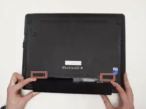
Place the laptop with the back case facing up.
-
Remove the external battery by sliding the latches towards each other.
-
Tilt the battery upwards and remove it from its socket.
-
-
-
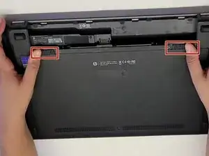
Rotate the computer 180 degrees.
-
Slide the release latches towards each other.
-
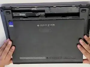
Lift the bottom door away from the direction of the battery socket.
-
-
-
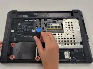
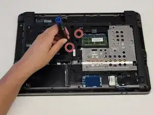
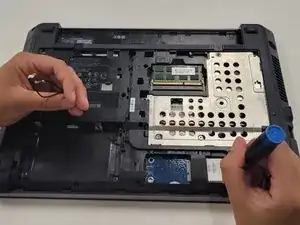
Remove the four 4.0 mm Phillips PM2.0×4.0 screws that secure the hard drive to the computer.
-
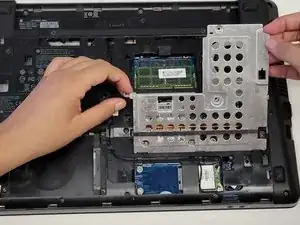
Slide the hard drive to the left and lift it away from the computer.
-
-
-
Remove the 6.0 mm Phillips PM2.5×6.0 screw that secures the optical drive.
-
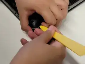
Using a spudger, push the optical drive tab to the left.
-
With your other hand gently pull the optical drive to the left.
-
-
-
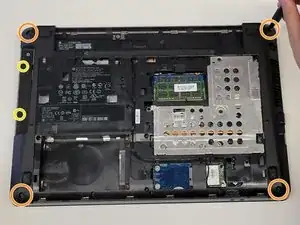
Use the spudger to remove four rubber screw covers from the corners of the laptop.
-
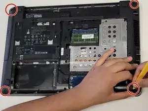
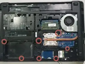
Remove four 6.0 mm Torx T8 M2.5×6.0 screws from the corners of the computer.
-
Remove two 2.5 mm Phillips PM2.0×2.5 screws from the optical drive bay.
-
-
-
Remove three 2.0 mm Phillips PM2.0×2.0 screws from the battery bay.
-
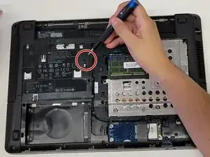
Remove one 3.0 mm Phillips PM2.0x3.0 security screw from the battery bay.
-
-
-
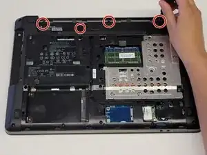
Remove three 6.0 mm Phillips PM2.5×6.0 screws that secure the heat shield to the computer.
-
Slightly slide the heat shield to the left and lift it away from the computer.
-
-
-
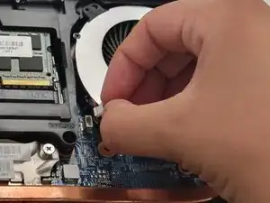
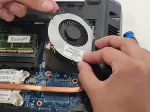
Disconnect the fan cable from the system board.
-
Remove one 5.0 mm Phillips PM2.5×5.0 screw that secures the fan to the system board.
-
Lift the fan and remove it at an angle.
-
-
-
Disconnect the 2 WLAN coaxial antenna cables from the terminals on the WLAN module by carefully prying up the connectors using your spudger or your hands
-
Remove the two 3.0 mm Phillips PM2.0×3.0 screws that secure the WLAN module.
-
Remove the WLAN module by pulling away to the right.
-
-
-
Place the computer right-side up.
-
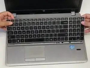
Place your hands over the keyboard, gently press down, and slide the keyboard towards yourself.
-
Gently pry the keyboard from the top.
-
Lift at an angle and only detach enough so you do not inadvertently detach the keyboard cable.
-
-
-
Rotate the keyboard until it rests on the palm rest.
-
Disconnect the keyboard cable by lifting the keyboard connector latch and then disconnecting the keyboard cable from the system board.
-
-
-
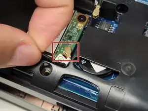
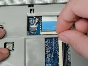
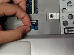
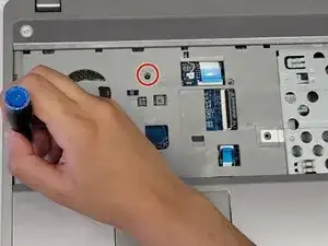
Disconnect the power button board cable by lifting the connector latch.
-
Using the blue tab, disconnect the cable from the system board.
-
-
-
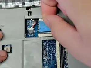
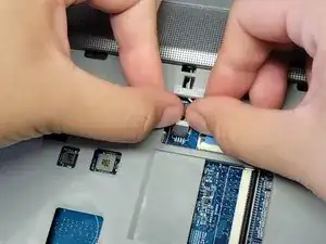
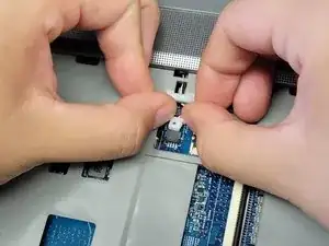
Disconnect the fingerprint reader board cable by lifting the keyboard connector latch.
-
Using the blue tab, disconnect the cable from the system board.
-
-
-
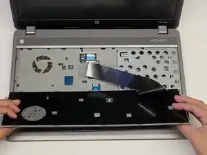
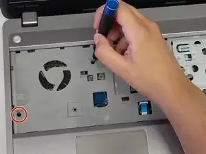
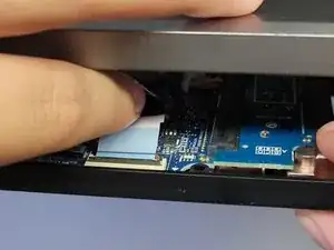
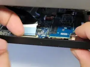
Using the spudger, pry between the top cover and bottom cover of the computer.
-
Remove the touchpad cable by lifting the latch and pulling on the blue tab.
-
-
-
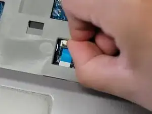
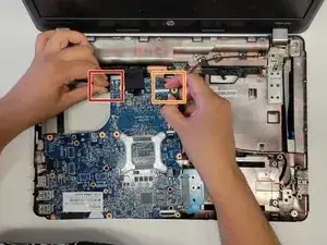
Unplug the USB connector cable by pinching the edge of the connector and pulling it away from the system board.
-
-
-
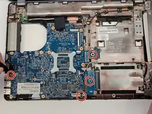
Disconnect the display cable by pinching the attached black tab and pulling it straight up.
-
Disconnect the power cable by pinching the cable firmly and pulling away from the connector.
-
Disconnect the battery connector cable by pinching the cable firmly and pulling away from the connector.
-
-
-
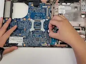
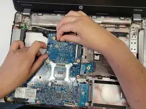
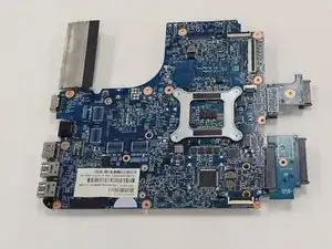
Once the system board is no longer attached to the computer, place it on a flat surface as shown in the picture.
-
Flip the system board over.
-
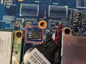
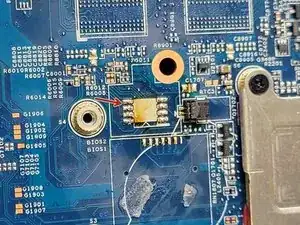
The BIOS chip is located at the bottom of the system board near the RTC battery.
-
-
-
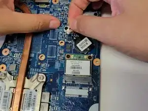
Unplug the Real-time clock (RTC) CMOS battery by gently pulling the battery cable away from the connector.
-
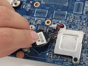
Grab the battery and gently pull it away from the system board.
-
-
-
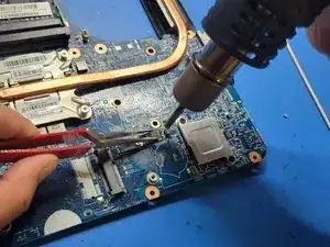
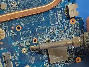
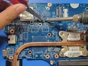
Place the new BIOS Chip and align the connectors with the pads.
-
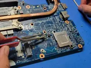
Gently apply pressure to the BIOS chip downwards using the rubber handle tweezers while soldering the connectors with the pads to ensure that the connectors on the BIOS chip have good contact with the pads.
-
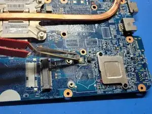
Do this until the BIOS chip is firmly in place
-
Check and ensure that the BIOS chip is firmly in place before reassembling the laptop.
-


To reassemble your device, follow these instructions in reverse order(starting from step 22).