Introduction
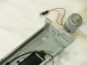
In this guide, you will be removing the drive motor of an HP Photosmart c3180 Printer, in order to either replace the drive motor itself or to replace the driving cable, per step 3. If the drive motor is burned out or is beginning to fail, the operation of your printer can be greatly or completely hindered.
The driving cabal appears to be made out of some kind of synthetic elastic material. Even though it can stretch a little, be careful not to stretch it too much and snap it.
-
-
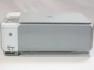
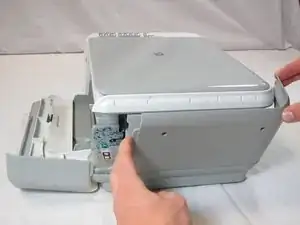
Rotate the printer 90 degrees counter clockwise so that the side panel next to control panel is facing you.
-
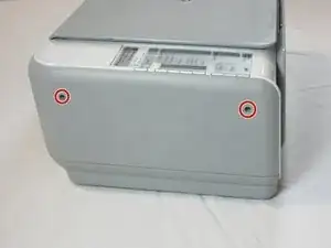
Remove the two T10 12mm Torx screws from the left side panel.
-
-
-
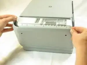
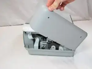
Firmly pull the the back of the side panel until it separates from the body of the printer.
-
Rotate the side panel upwards while pulling it towards yourself to remove the panel.
-
-
-
Rotate the printer 90 degrees clockwise.
-
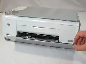
Grasp the paper tray and rotate it down.
-
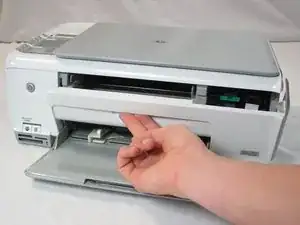
Insert your fingers into the slot in the printer door and pull to rotate the gate down.
-
-
-
Rotate the printer 90 degrees clockwise.
-
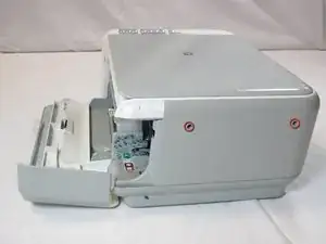
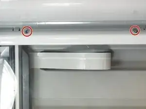
Remove the two T10 12 mm Torx screws.
-
Grasp both sides of the side panel and pull it forward to remove the panel.
-
-
-
Rotate the printer 90 degrees counter clockwise.
-
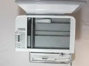
Lift the scanner lid to expose the scanner glass.
-
-
-
Rotate the printer 90 degrees counter clockwise.
-
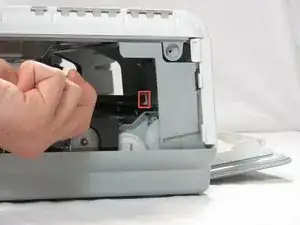
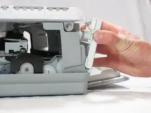
Inside the printer is a small white tab. Press it inward with a spudger until a pop is heard.
-
Remove the front panel by grasping its front and pulling away from the printer.
-
-
-
Rotate the printer 90 degrees clockwise.
-
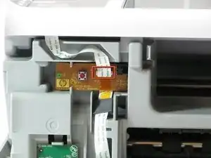
Remove the cable connecting the top panel of the printer to the power button assembly.
-
-
-
Set aside the top panel of the printer.
-
Remove the two T10 12 mm Torx screws from the top front of the printer
-
-
-
Rotate the Printer 90 degrees counter clockwise.
-
Remove the scanner cable from the main circuit board.
-
-
-
Rotate the printer 90 degrees clockwise.
-
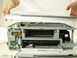
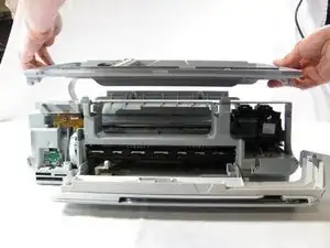
Using both hands, lift the scanner tray from the body of the printer.
-
-
-
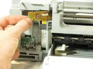
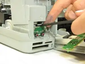
Remove the power button circuit board from the support frame by pinching the left side, and pulling forward and to the left simultaneously.
-
Push up on the tab holding the secondary control circuit board with the spudger and pull it forward to remove it.
-
-
-
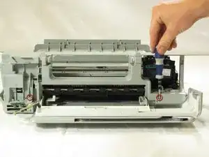
Remove the two T10 12 mm Torx screws.
-
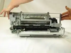
Lift the support frame off of the printer body with both hands.
-
-
-
Remove the printer door and paper tray by putting them in the closed position and not laying flat then rotating them upwards lift the left side up.
-
-
-
Remove both of the ink cartridges by grabbing the front of the ink cartridge and pulling down.
-
-
-
Remove the T10 6 mm Torx screw on the left side of the track assembly.
-
Remove the T10 12 mm Torx screw on the left side of the track assembly.
-
-
-
Rotate the printer 90 degrees counter clockwise.
-
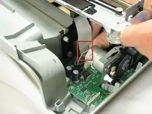
Remove the cable connecting the ink cartridge carriage to the main circuit board.
-
-
-
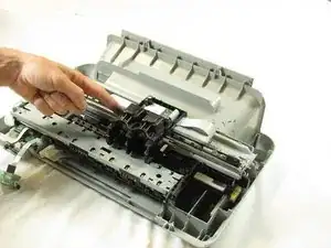
Slide the ink cartridge carriage all the way to the right side of the printer.
-
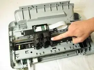
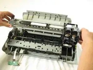
Using both hands, carefully lift the ink cartridge track off of the main body of the printer.
-
-
-
Set aside the printer body.
-
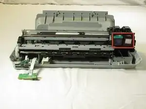
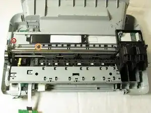
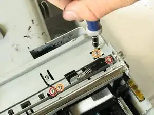
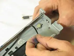
Remove the two motor retainment T10 4 mm Torx screws, per images 1-2.
-
-
-
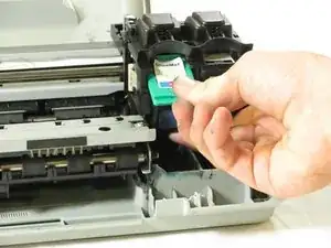
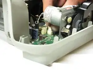
Grasp the bottom of the drive motor (Hidden behind the housing in images 1-2) and rock it away from the center of the cable loop to release the tension in the cable.
-
Using your fingers, unhook the cable from drive motor.
-


To reassemble your device, follow these instructions in reverse order. Take your e-waste to an R2 or e-Stewards certified recycler.
One comment
Wo geht das Flachbandkabel F1 hin?