Introduction

This is a guide on how to replace the motherboard in your HP 15-g029wm. This guide may be needed if you're encountering problems with your HP 15-g029wm shutting down randomly. You will need to know how to remove the heatsink, clock battery, and RAM. This is because it will not be shown in this guide and these components will be needed for your new motherboard.

  1. L1mvMIFD6dnsx3wE
    • Unplug any charging cord or accessories connected to the device before beginning.

  2. HYZNZDhWbgAZ1XIu
    • Place the laptop bottom-side up on a secure, flat surface.

  3. rfcESNBDQb4GSsBF
    rfcESNBDQb4GSsBF
    cRy6FhROsYRmCcUD
    FWCI6xnnLvyrHceD
    • Slide each of the two switches that secure the battery to the left.

    • This will reveal an image of an unlocked lock.

  4. KOCkBxLGybMC4nE3
    KOCkBxLGybMC4nE3
    URF1YoapUg1W1jPL
    QmfALseeldUZxHAg
    • Use your hands to gently pull the disconnected battery out of the device.

    • When inserting the new battery, pay special attention to align the battery connections correctly.

  5. fxrPI2lK1sHoUnD6
    fxrPI2lK1sHoUnD6
    V6DJI1mqtVwRBfyJ
    • Remove the following Phillips screws on the lower case:

    • Nine 5 mm

    • One 6 mm

    • This will allow the optical drive to separate from the chassis.

  6. hmLh6OVxAUViBe1N
    • Slide the optical drive directly out of its slot.

  7. OctAX5ORKpnZQXuX
    • Remove the two 2 mm Phillips screws on the lip of the optical drive slot.

  8. EPLBcSQHGXbfEb5P
    EPLBcSQHGXbfEb5P
    mloYwQqEXRMEbXSI
    5KRylwOEaB41QsEM
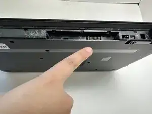
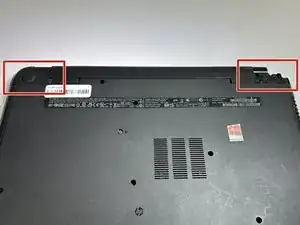
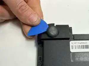
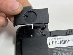
    • Use an opening pick to remove the two circular rubber feet near the laptop hinges.

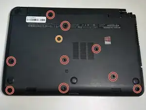
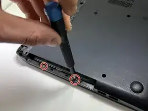
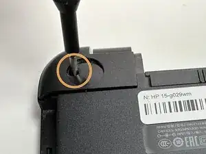
    • Remove both of the 8 mm Phillips screws.

    • The screws were hidden by the rubber feet.

  9. xuGcKWLIa4wSDmvm
    xuGcKWLIa4wSDmvm
    coVNRRDorK2A2KqV
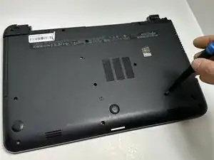
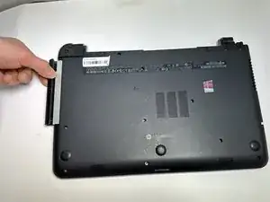
    • Use an opening pick to pry up and remove the left hinge cover.

    • Use an opening pick to pry up and remove the right hinge cover.

  10. NKKDHWni124Q2FqM
    NKKDHWni124Q2FqM
    UaaL2XDevmsEV2FM
    YJgLJ6NZoGaadNfJ
    • Flip the device face up and open the lid.

    • Insert an opening pick under the keyboard and pry around the perimeter of the keyboard until it fully releases.

    • Lift the keyboard slightly.

    • There is a ribbon cable connecting the keyboard to the device on the underside. Do NOT pull it away or you risk ripping the ribbon cable and causing damage.

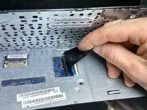
    • Use your fingers or an opening pick to unlock the ZIF locking flap that secures the keyboard ribbon cable.

    • Disconnect the keyboard ribbon cable.

    • Lift the keyboard off.

  11. JccwEOU4ykyRDHFS
    JccwEOU4ykyRDHFS
    bFXCW5oAIEv1epbQ
    TVLDtmDJEAqKPbch
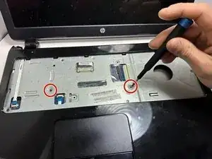
    • Remove two 5 mm screws using a Phillips screwdriver.

    • Insert an opening pick in the seam between the top case and chassis.

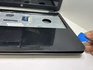
    • Slide the opening pick around the edge of the device to separate the top case from the chassis.

    • Slightly lift the top case up and away from the chassis.

    • There is a ribbon cable connecting the top plate to the device. Handle with care, and do NOT yank on the ribbon cable to prevent damage.

  12. CofZwsRSxUeNMDPe
    CofZwsRSxUeNMDPe
    jSZWpDfjCQ1qxxPI
    WTZUCJ1gUMFIcSHO
    • Use your fingers or an opening pick to flip up the black ZIF locking flap.

    • Disconnect the ribbon cable.

    • Lift off the top case.

  13. ewNDkkRaJ5evJHvY
    ewNDkkRaJ5evJHvY
    NUvP5JKHEPYQVpUD
    • Use a Phillips screwdriver to remove the three 5 mm screws that secure the fan.

  14. ZilA4CrpMslaSfsW
    ZilA4CrpMslaSfsW
    f3SJmb5E3pbRTgDL
    • Gently "walk" the fan connector directly out of its motherboard socket.

    • Do not pull on the wires.

  15. 4hAKPaqVYsorSHMK
    • Lift the fan up and out of the chassis.

  16. BNugfAFhIhXBIuBQ
    BNugfAFhIhXBIuBQ
    FuSHDGlltcNm6ChI
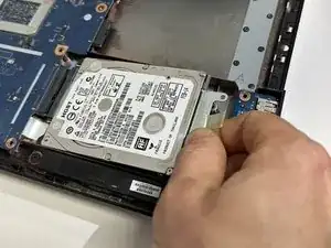
    • Remove the two 5 mm Phillips screws that secure the HDD.

    • Pull the HDD slightly to the right to disconnect it, then lift it up and out of the chassis.

  17. bDed6dZkSsUcJF1y
    bDed6dZkSsUcJF1y
    tIYA3EcwQdED1IRY
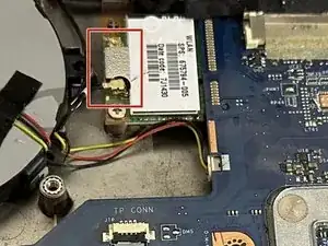
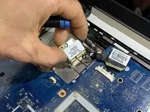
    • Use the tip of a spudger to pry up and disconnect the two antenna cables attached to the wireless card.

  18. jyw44fwZILBjnvgq
    jyw44fwZILBjnvgq
    XH5sQxNPmOCXdayE
    f3RFpR4MAXWhkh4H
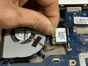
    • Remove the single 3 mm Phillips screw that secures the wireless card.

    • Pull the wireless card out of its socket.

  19. ELeDCALAuRJvnIwH
    ELeDCALAuRJvnIwH
    NWOekDmWfgrFD6SK
    MeUbvTSgkvC1kaHE
    • Use two opening picks to disconnect the display cable.

  20. JLAdSQycu3FJC41B
    • Use an opening pick to gently "walk" the white speaker connector directly out of its port.

  21. bXdODJw1fwPVnGKu
    bXdODJw1fwPVnGKu
    tfDssZVVpNcZetLg
    1GJM6C2DWaJgL3IX
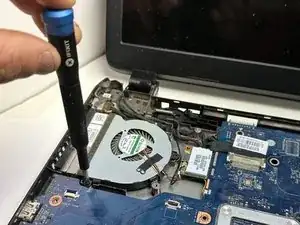
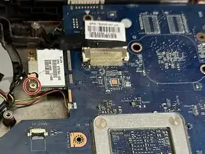
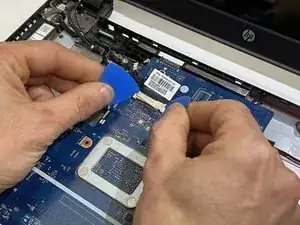
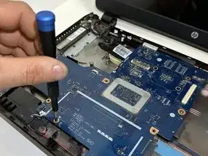
    • Remove the four 3 mm screws that secure the motherboard.

    • Lift the front edge of the motherboard slightly.

    • There is a ribbon cable connecting the motherboard to the device chassis. Do not yank it away.

  22. vQB4EWP2tgLAK2X4
    vQB4EWP2tgLAK2X4
    5aVEcItZyAeZkn3m
    aEI3AnsZMkSogOtH
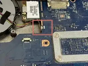
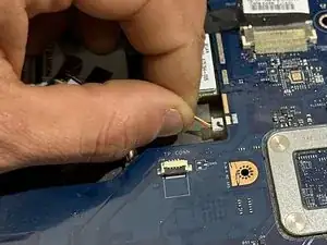
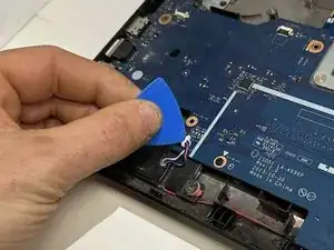
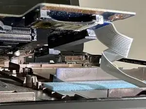
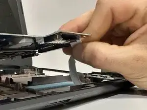
    • Use an opening pick or your fingers to release the ZIF locking flap.

    • Pull the ribbon cable out of its port.

  23. 16OEw1AlNc2TQMRI
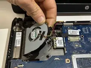
    • The motherboard is now fully disconnected and able to be removed from the chassis by lifting it out with your hands.

    • Remove the following components for your new motherboard: Heatsink, RAM, CMOS battery.

Conclusion

To reassemble your device, follow these instructions in reverse order.

Syrinity/Ezyra/Ezra

Member since: 29/01/24

396 Reputation

0 comments