
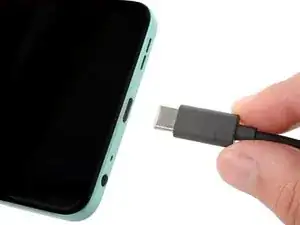
Introduction
Follow this guide to replace a broken, cracked, or non‑responsive screen on your HMD Pulse Pro smartphone.
This guide is for the screen and frame assembly—the screen pre‑installed on a frame—not a screen panel on its own. You'll be removing and transferring all the parts from your old phone into the new assembly.
If your battery is swollen, take appropriate precautions.
-
-
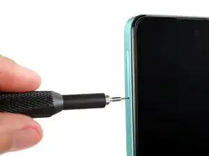
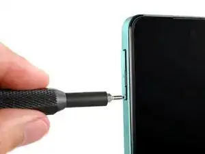
Firmly press a SIM eject tool, bit, or straightened paper clip into the SIM card tray hole on the left edge of your phone until the tray ejects.
-
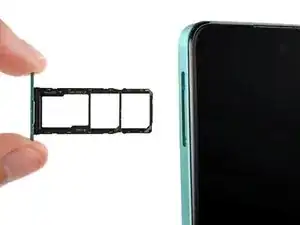
Remove the SIM card tray.
-
-
-
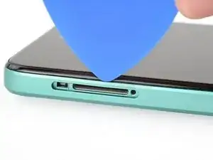
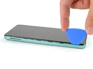
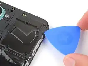
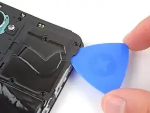
Insert the tip of an opening pick between the back cover and frame, at the SIM card tray cutout.
-
-
-
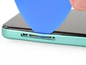
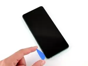
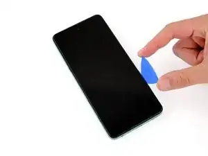
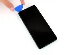
Position the opening pick straight down and slide it along the left edge to begin unclipping the back cover.
-
-
-
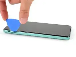
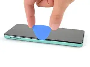
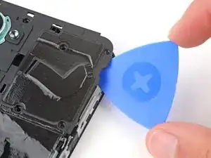
Continue sliding the pick around the perimeter of your phone until the back cover is fully unclipped.
-
-
-
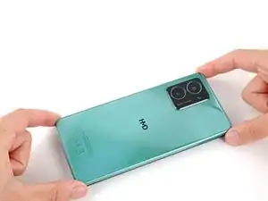
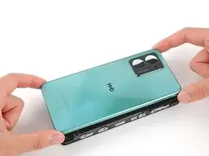
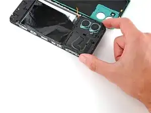
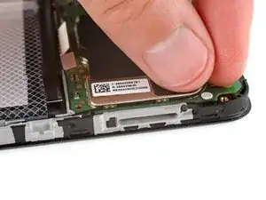
Carefully flip your phone over so the back cover is facing up.
-
Lift the back cover off the frame and flip it over the left edge of your phone, laying the cover flat on your work surface.
-
-
-
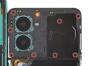
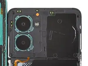
Use a Phillips screwdriver to remove the nine 3.6 mm‑long screws securing the motherboard cover.
-
-
-
Insert an opening pick between the right edge of the motherboard cover and frame.
-
Twist the pick to fully unclip the cover.
-
-
-
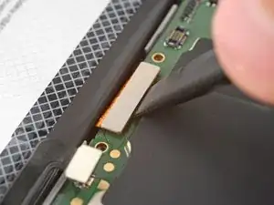
Use the flat end of a spudger to pry up and disconnect the battery press connector from the bottom edge of the motherboard.
-
-
-
Use the flat end of a spudger to pry up and disconnect the back cover press connector from the bottom edge of the motherboard.
-
-
-
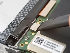
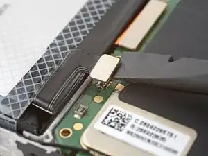
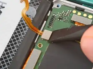
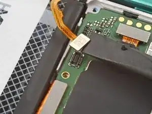
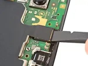
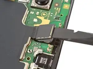
Use the flat end of a spudger to pry up and disconnect the display cable press connector, next to the battery cable.
-
-
-
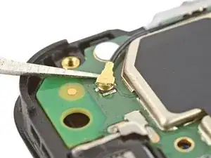
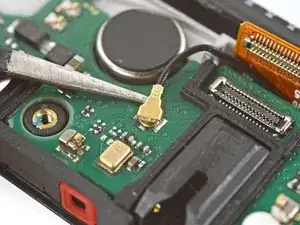
Slide one arm of a pair of tweezers under the metal neck of the black antenna cable's connector head, near the top right corner of the motherboard.
-
Lift straight up to disconnect the cable.
-
-
-
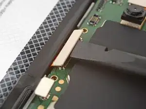
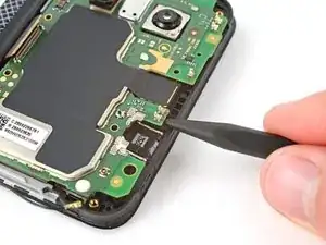
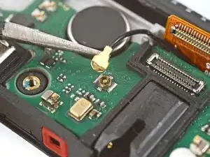
Insert the flat end of a spudger under the top edge of the front camera and gently lift it out of its recess.
-
-
-
Use the point of a spudger to pry up the bottom right corner of the motherboard until it unclips.
-
If the board still feels stuck in place, use the spudger to pry up the top edge.
-
-
-
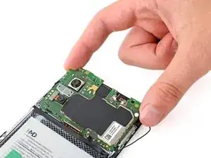
Lift and remove the motherboard.
-
The front camera may have disconnected from the bottom of the board during removal. If it did, reconnect its press connector.
-
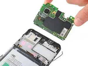
Make sure the two press connectors on the bottom edge and the antenna cable on the right edge are out of the way so they don't get trapped underneath the board.
-
Lower the board into its recess and press down on the edges to clip it into place.
-
-
-
Use the flat end of a spudger to scrape off any large chunks of thermal paste from the bottom of the motherboard.
-
Use a pipette or syringe to apply a drop of isopropyl alcohol (>90%) to the thermal paste residue.
-
Wipe away all the residue with a coffee filter or lint-free cloth. Wait one minute to allow the alcohol to completely dry.
-
Apply a small bead of thermal paste to each of the four plus (+) signs that are lightly engraved in the frame.
-
-
-
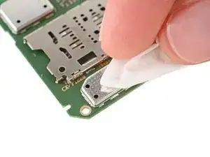
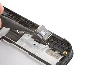
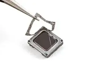
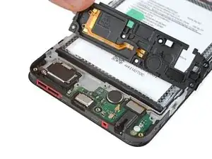
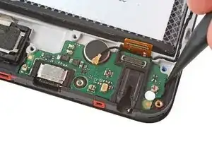
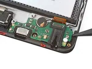
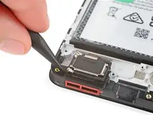
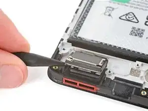
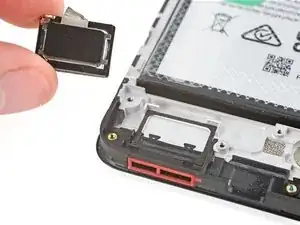
Use a spudger to pry up the earpiece speaker from the bottom edge of your phone.
-
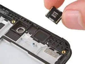
Remove the speaker.
-
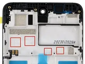
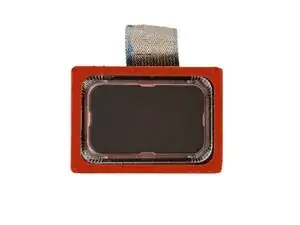
Remove the plastic liner from the earpiece speaker adhesive on the screen and frame assembly.
-
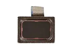
Push the speaker into place so the raised ends of its metal contact arms are on the bottom edge.
-
-
-
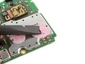
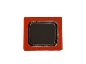
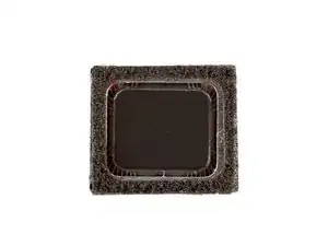
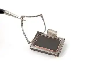
Use tweezers to carefully remove the layer of foam adhesive from the perimeter of the earpiece speaker's underside.
-
Discard the adhesive—it can't be reused.
-
-
-
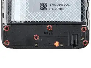
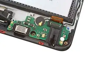
Use a Phillips screwdriver to remove the seven 3.6 mm‑long screws securing the charging board cover.
-
-
-
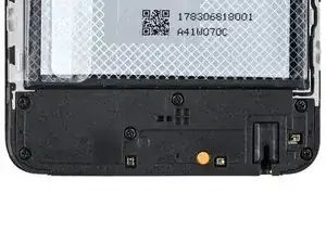
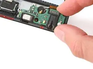
Use your fingers to lift the bottom edge of the charging board cover until it unclips.
-
Remove the cover.
-
-
-
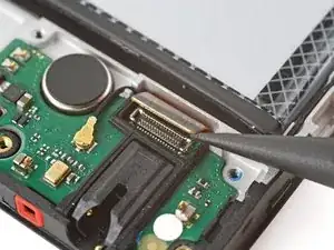
Use the point of a spudger to pry up and disconnect the charging board cable press connector on the top edge of the board.
-
-
-
Slide one arm of a pair of tweezers under the metal neck of the black antenna cable's connector head, near the center of the board.
-
Lift straight up to disconnect the cable.
-
-
-
Use the point of a spudger to pry up and unclip the left and right edges of the charging board.
-
-
-
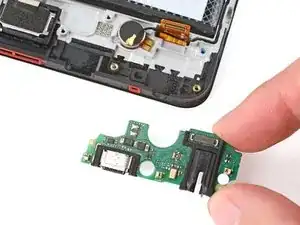
Remove the charging board.
-
Make sure the interconnect cable is flipped up and the black antenna cable is routed through its groove on the right edge.
-
Set the charging board into its recess and press down on the edges to clip it into place.
-
-
-
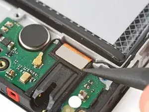
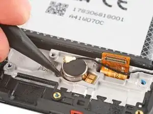
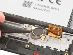
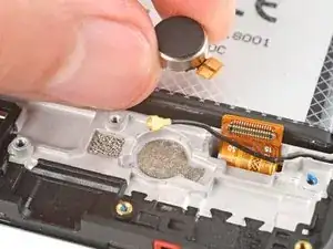
Insert the point of a spudger under the left side of the vibration motor (near the small notch) and pry it up.
-
Remove the vibration motor.
-
-
-
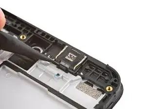
Insert the point of a spudger under the bottom left corner of the loudspeaker and pry it up.
-
Remove the loudspeaker.
-
Remove the plastic liner from the loudspeaker adhesive on your replacement screen and frame assembly.
-
Push the speaker into place so the metal contacts are on the left edge.
-
-
-
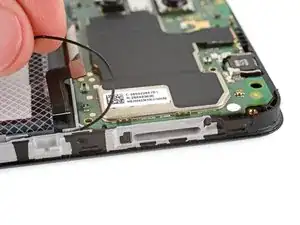
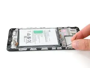
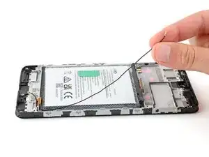
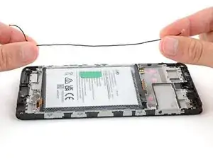
Use your fingers to lift the black antenna cable out of its groove on the right edge of your phone.
-
-
-
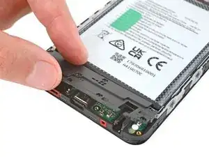
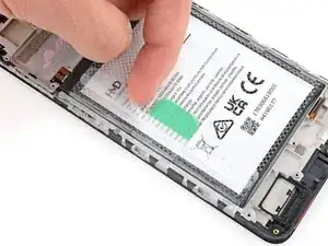
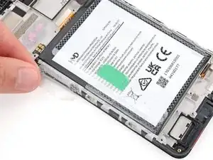
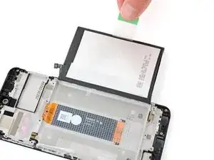
Use your fingers to carefully peel the three plastic tabs from the left side of the battery.
-
-
-
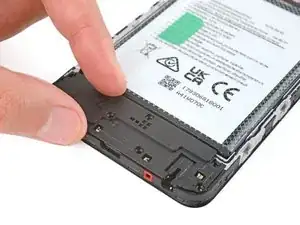
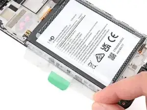
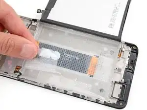
With one hand, fold the clear outer tabs out of the way of the battery and firmly hold them down to secure the frame.
-
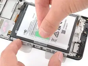
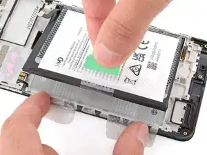
With your free hand, grip the center, green pull tab and pull straight up to fully separate the battery adhesive.
-
Lay the battery over the right edge of your phone.
-
-
-
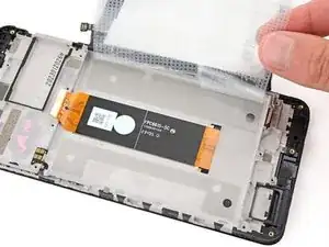
Remove the battery and its film.
-
If you're reusing the original battery:
-
If the plastic battery film was damaged during removal, carefully remove it—be very cautious not to bend or damage the battery in any way. Apply new film to the battery, making sure the tabs go on the left edge.
-
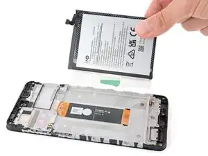
Remove the two large plastic liners from the outer edges of the battery recess to expose the adhesive.
-
Firmly press the battery into its recess so the cable is on the top edge.
-
-
-
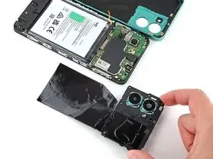
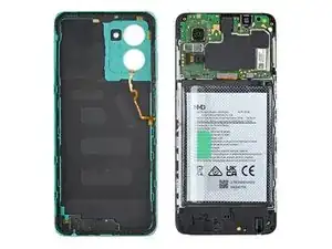
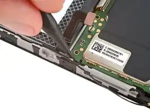
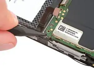
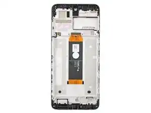
You're left with the screen and frame assembly.
-
Remove the large liner under the display cable in your new screen and frame assembly.
-
Firmly press the display cable into place to secure it with the adhesive.
-
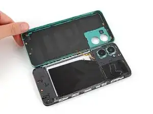

Compare your new replacement part to the original part—you may need to transfer remaining components or remove adhesive backings from the new part before you install it.
To reassemble your device, follow these instructions in reverse order. You'll be transferring all the parts to your new screen and frame assembly.
If you replaced your battery, calibrate it after completing this guide for optimal performance.
Take your e-waste to an R2 or e-Stewards certified recycler.
Repair didn’t go as planned? Try some basic troubleshooting, or ask our Answers community for help.

One comment
I have one case for liquid damage. How can i get its bitmap?