Introduction

Use this guide to replace the charging board in your HMD Fusion phone.

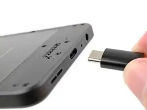
The charging board includes the USB-C port and headphone jack. To replace either of the ports, you must replace the entire board.

If you're having issues charging your phone, connecting headphones via the 3.5 mm jack, or if either port is loose, it may be time to replace the charging board.

  1. gRLIAsTp3Wkom4dj
    • Let your phone's battery drain below 25% before starting this repair. A charged lithium‑ion battery may catch fire if damaged.

    • Unplug all cables from your phone and completely power it down.

  2. IeoZUYvqlZnCUenT
    IeoZUYvqlZnCUenT
    OvUMFE2G5Zmx5GOi
    IWjaZJoBSTjTIPPP
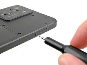
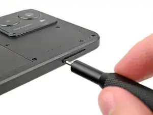
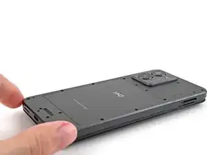
    • Firmly press a SIM eject tool, bit, or straightened paper clip into the SIM card tray hole on the left edge of your phone until the tray ejects.

    • Remove the SIM card tray.

  3. WfSZNgJuNdgv5YuF
    WfSZNgJuNdgv5YuF
    xeX4fGknaAU6EYI6
    jbL25tCYJr1jIRQs
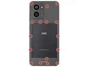
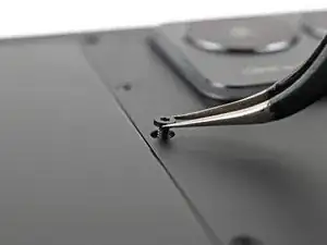
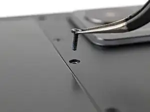
    • Use a T3 Torx screwdriver to remove the sixteen 5.0 mm‑long screws securing the back cover.

    • Use your fingernails, or angled tweezers, to remove any stuck screws.

    • The screws are secured tightly in the back cover, so you might not be able to remove all of them. If you can't remove a few screws, don't worry! Move to the next step and follow the guide normally.

  4. 5kLbZMElWlN4GcW6
    • During the next four steps, the remaining back cover screws might fall out unexpectedly.

    • To avoid losing screws, you can place a tray, bowl, or Magnetic Project Mat under the phone while you work.

  5. i3sSSOBKOhaCK5US
    i3sSSOBKOhaCK5US
    x2knZUqLfBVKbeMO
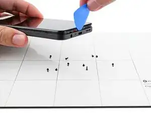
    • Flip your phone over so the screen is facing up.

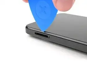
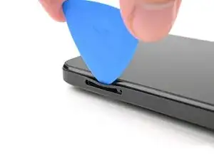
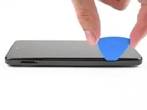
    • Insert the tip of an opening pick between the back cover and frame at the SIM card tray cutout.

  6. AIL3VLwPGWEEVtPO
    AIL3VLwPGWEEVtPO
    yiAXUuuVGaAVPNa6
    o2WmEOSmZbFFLuFb
    • Slide the opening pick along the left edge to begin unclipping the back cover.

  7. OBOAVjReajSurmBV
    OBOAVjReajSurmBV
    jawTxxR5hiCyicRv
    VUETOMNHAKJFK4eY
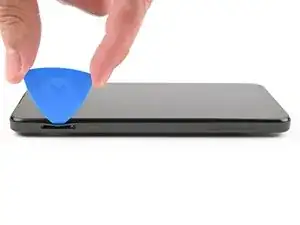
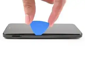
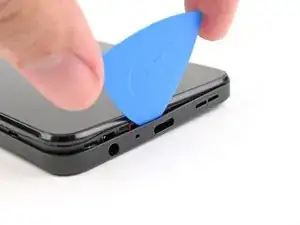
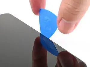
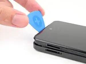
    • Continue sliding the pick around the perimeter of your phone until the back cover is fully unclipped.

    • The corners can be tricky to unclip and may take some force. If you're having trouble, try prying up with the pick.

    • Don't try to fully remove the cover yet, as it's still connected by a delicate cable.

  8. mP2q2X1hHTkvnTLJ
    mP2q2X1hHTkvnTLJ
    MNLkULEhGIrsBaPT
    afAGxRVMpenTmvjq
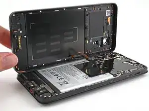
    • Carefully flip your phone over so the back cover is facing up.

    • Lift the back cover off the frame and flip it over the left edge of your phone, laying the cover flat on your work surface.

    • Be very careful not to strain the back cover's delicate cable.

    • During reassembly, place the back cover onto the frame and firmly press around the perimeter to reengage all the clips.

  9. XCwtQ4dfNpGbxb2k
    XCwtQ4dfNpGbxb2k
    USKBePQUqcuZyQfQ
    tNYJu5eO1rLX2OdO
  10. K35AyWkngrn1TNxL
    K35AyWkngrn1TNxL
    MAHaRLN2KP2IWJqX
    F464cWuK3nwDppjG
    • Use a spudger to pry up and disconnect the power button press connector.

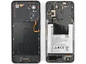
    • Remove the back cover.

  11. lUm2ibCclTCRnvUR
    lUm2ibCclTCRnvUR
    UDvWkErFihPFGhl1
    • Be careful not to puncture or damage the battery with your tool during the rest of this guide.

    • Use a T3 Torx screwdriver to remove the three 3.4 mm‑long screws securing the loudspeaker.

    • One of the screws on the loudspeaker may be covered by a sticker. Pierce through it with your screwdriver, or use tweezers to remove it.

  12. JqwGxHJVLbQynvVP
    JqwGxHJVLbQynvVP
    eKltjTbd3FoxifRj
    GmruJlesYQsQ1dH2
    • Use your fingers to lift the loudspeaker out of the frame by its metal bracket.

    • Remove the loudspeaker.

  13. MD4TbgRqaitZg1po
    MD4TbgRqaitZg1po
    EuAgCGeNLYs5DAlR
    EgreP3vUfmhIcy2U
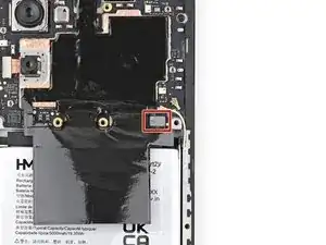
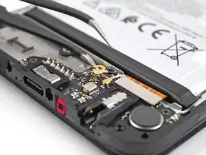
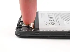
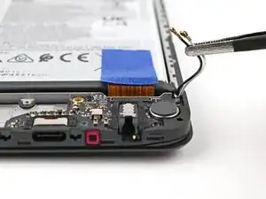
    • Slide one arm of a pair of tweezers under the metal neck of the black antenna cable's connector head, near the center of the board.

    • Lift straight up to disconnect the cable.

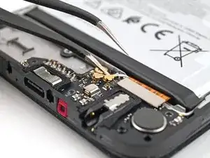
    • Repeat for the white antenna cable.

    • To reconnect the cable, hold the metal head over its socket and press down with the flat end of a spudger—it should snap into place. If it's not connecting, reposition the head and try again.

  14. 3sSUYATaiWbDdVni
    3sSUYATaiWbDdVni
    BWeIVNRqWTO4Mdij
    • Use a spudger to pry up and disconnect the interconnect cable press connector.

  15. MsWLw4IRmR4j2nTP
    MsWLw4IRmR4j2nTP
    QuXeefTKSauAMgDV
    4DLEmOALZEZIEaVq
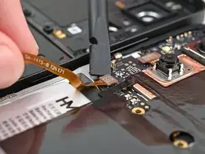
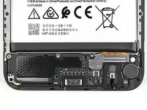
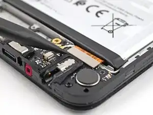
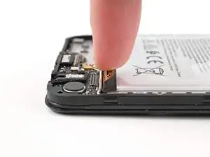
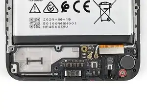
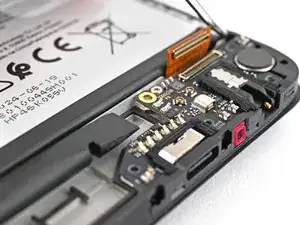
    • Move the interconnect cable press connector toward the battery to keep it out of the way of the charging board in the next step.

    • You can use tape with light adhesive (such as painter's tape) to keep the cable out of the way.

  16. SRonwBPukmaFdPZp
    SRonwBPukmaFdPZp
    WwglWF4vKYgqGma6
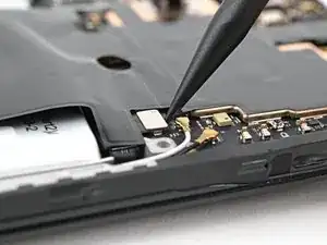
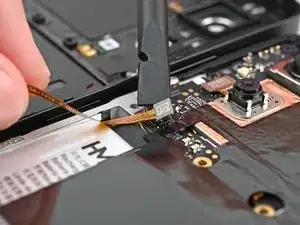
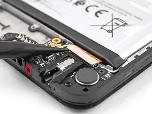
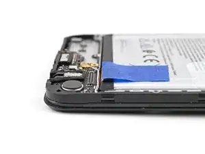
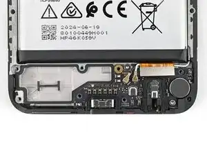
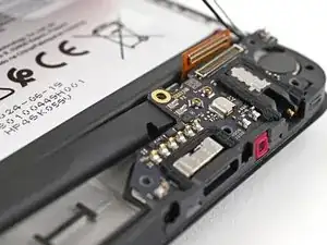
    • Use tweezers, or your fingers, to move the two antenna cables out of their slots near the top edge of the charging board.

  17. xi2GvkVcKWsqvSUA
    xi2GvkVcKWsqvSUA
    RlQAw1p5DSZ5L4ig
    • Use a T3 Torx screwdriver to remove the 3.3 mm‑long screw securing the charging board.

  18. utTtMedIImQUvHES
    utTtMedIImQUvHES
    O1gq1vooblrYRUn1
    eFMo3r25LThVSEoR
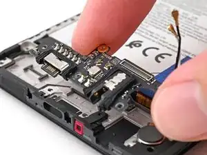
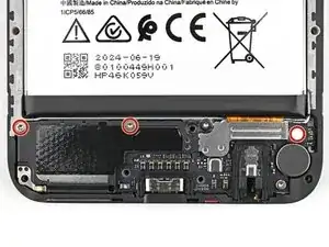
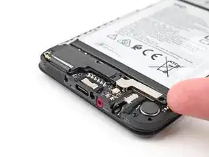
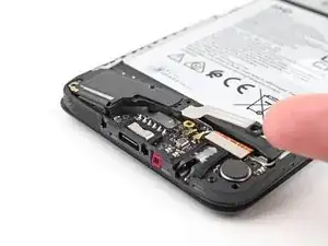
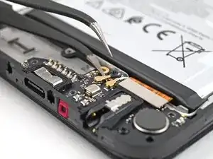
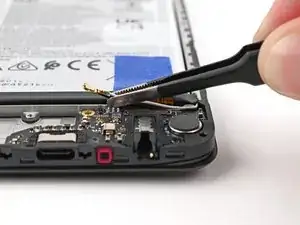
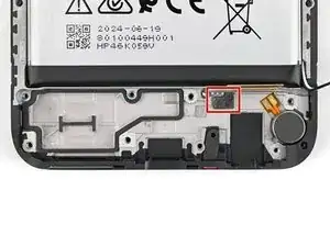
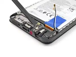
    • The top edge of the charging board is adhered to the frame.

    • Insert the flat end of a spudger under the top left edge of the charging board, next to the antenna cable connectors.

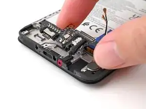
    • Slide the spudger under the charging board to separate the adhesive.

  19. YBsQ4ZdGgbifteUK
    YBsQ4ZdGgbifteUK
    16KpOMFHiSfoRcJt
    BRElkFFVWBmwRLTl
    • Lift the charging board out of the frame and remove it.

    • During reassembly, insert the USB-C port into its slot before pressing the charging board flat to the frame.

Conclusion

To reassemble your device, follow these instructions in reverse order.

Take your e-waste to an R2 or e-Stewards certified recycler.

Repair didn’t go as planned? Try some basic troubleshooting, or ask our Answers community for help.

Alex Diaz-Kokaisl

Member since: 16/01/22

151892 Reputation

0 comments