Introduction

This repair guide was authored by the iFixit staff and hasn’t been endorsed by Google. Learn more about our repair guides here.

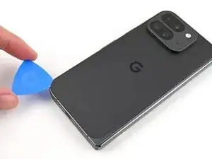
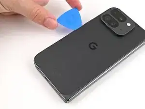
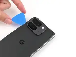
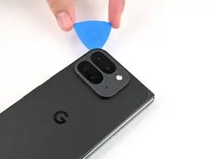
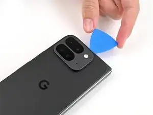
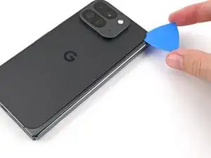
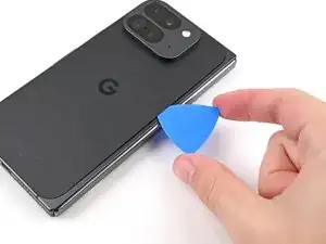
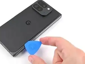
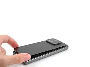
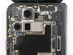
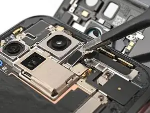
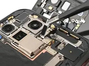
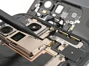
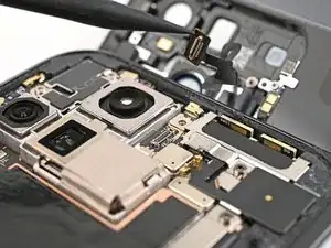
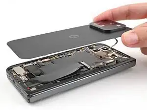
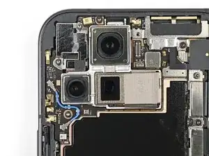
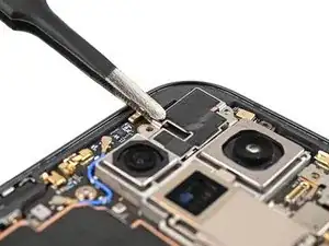
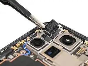
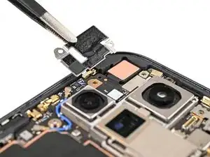
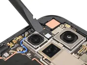
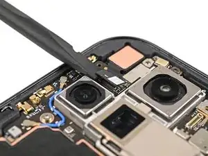
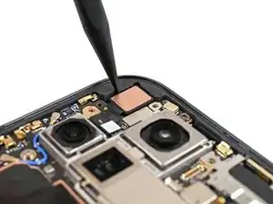
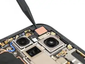
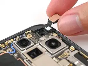
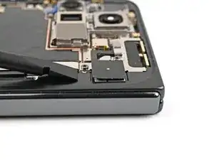
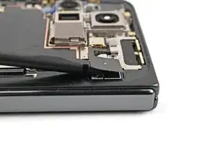
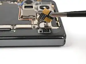
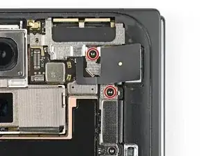
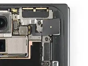
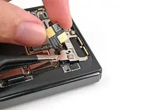
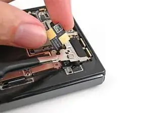
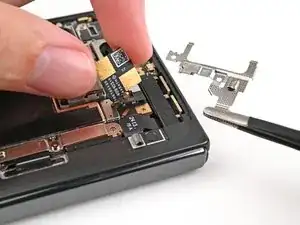
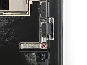
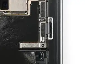
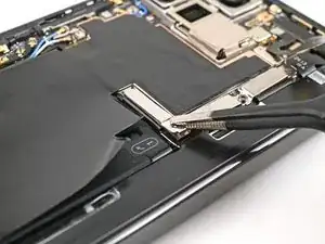
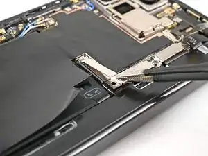
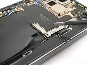
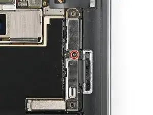
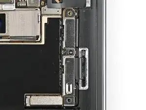
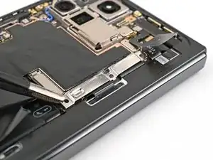
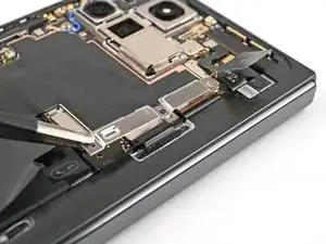
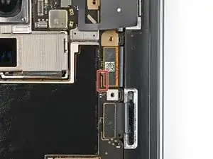
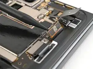
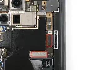
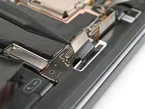
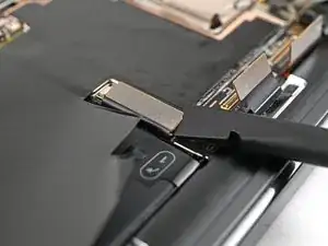
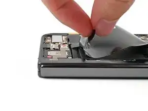
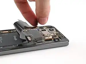
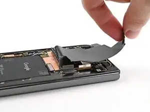
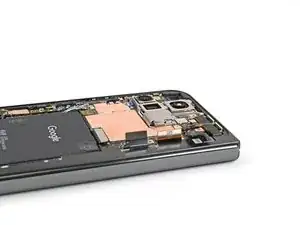
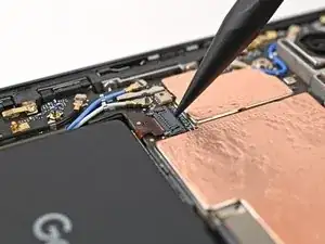
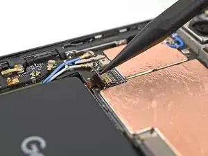
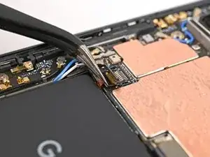
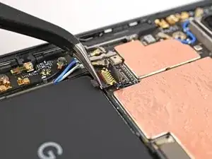
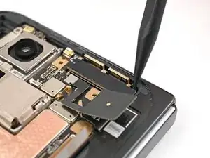
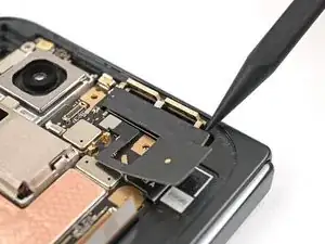
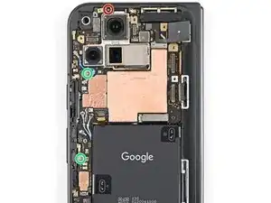
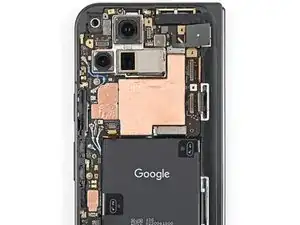
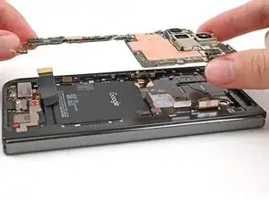
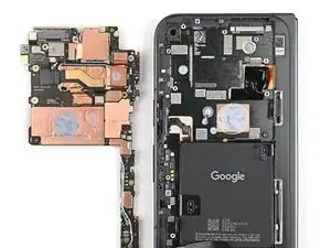
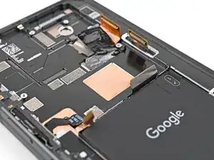
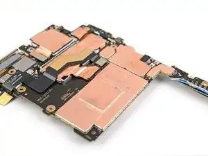
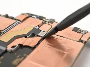
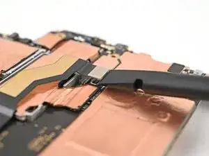
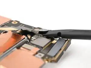
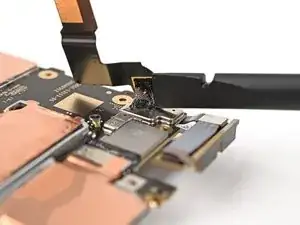
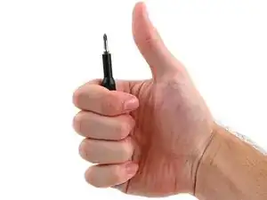
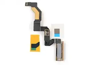
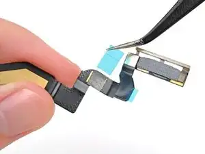
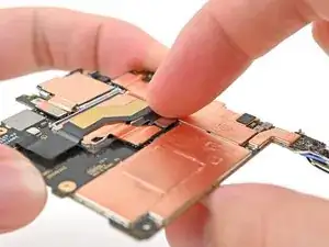
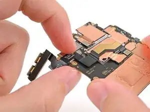
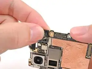
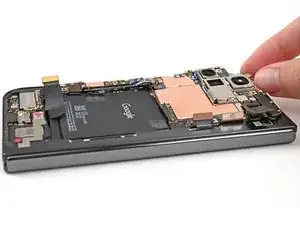
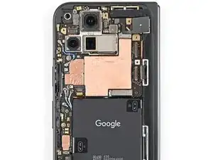
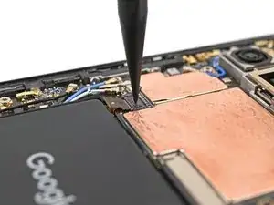
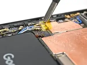
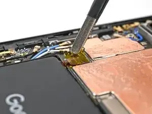
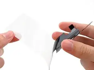
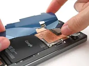
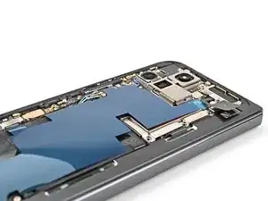
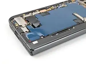
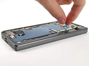
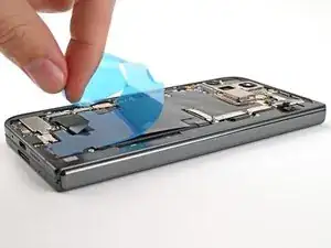
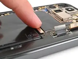
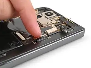
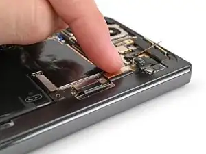
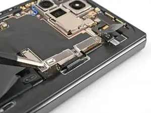
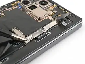
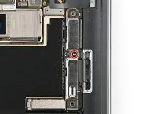
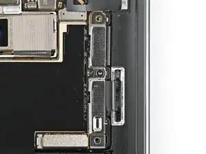
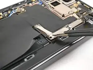
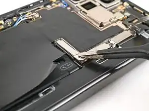
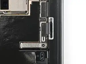
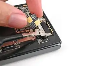
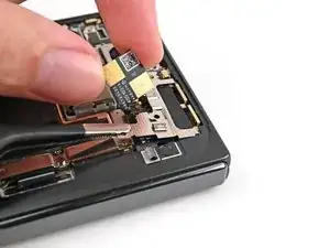
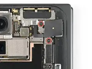
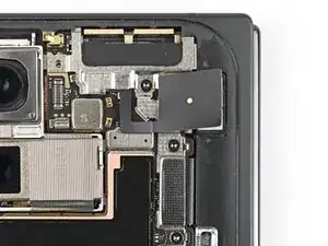
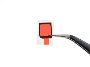
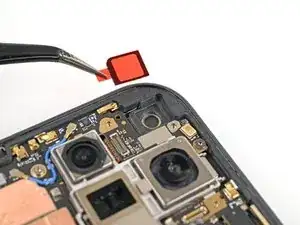
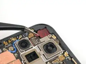
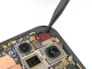
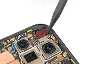
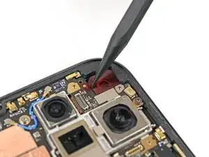
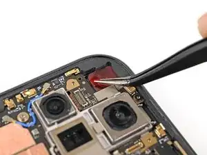
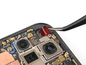
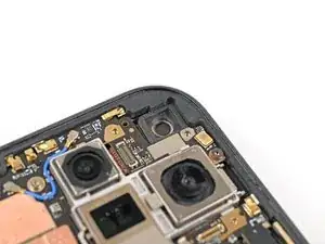
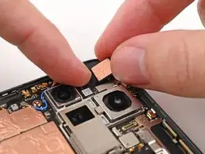
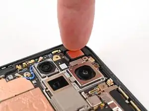
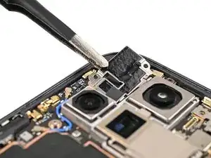
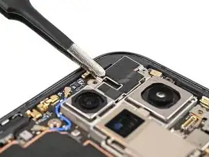
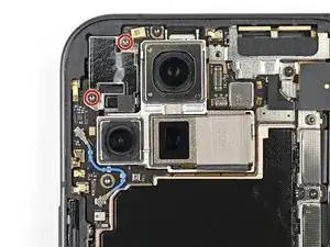
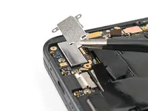
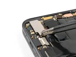
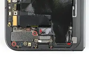
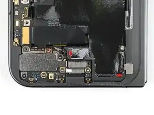
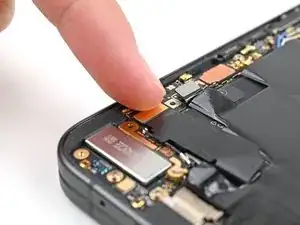
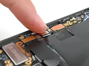
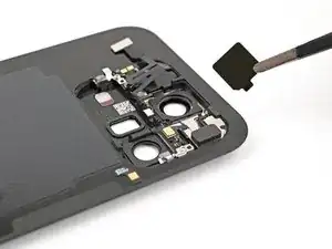
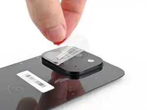
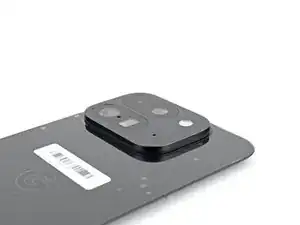
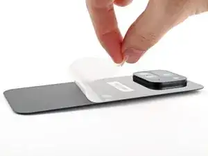
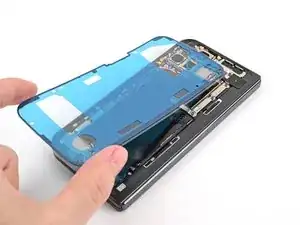
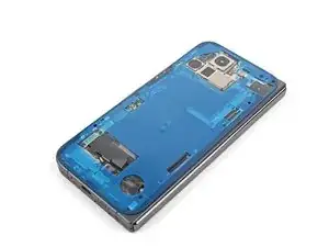
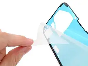
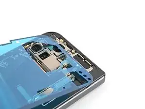
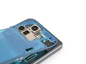
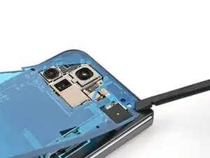
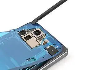
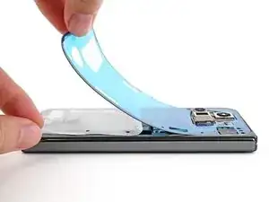
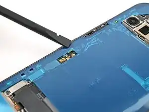
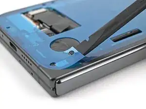
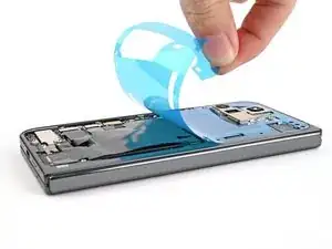
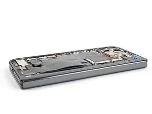
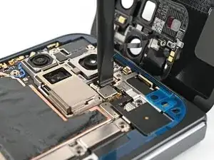
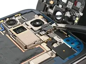
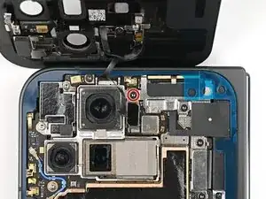
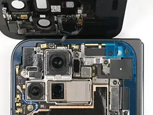
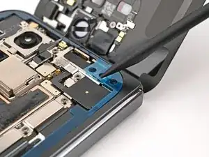
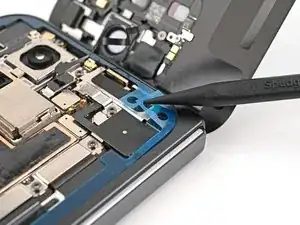
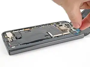
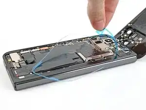
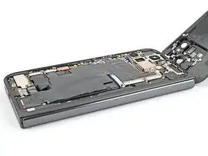
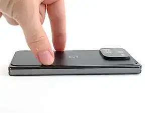
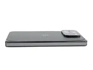
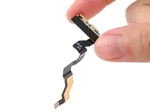
Use this guide to replace the 5G mmWave antenna in your Google Pixel 9 Pro Fold.

  1. oJjMp1p2qPpIDZAJ
    • Let your phone's battery drain below 25% before starting this repair. A charged lithium‑ion battery may catch fire if damaged.

    • Unplug all cables from your phone and completely power it down.

  2. eTmJydwESkDseema
    eTmJydwESkDseema
    aa3qhEvEDj6yHm11
    jbuhiFDgPymVlJQD
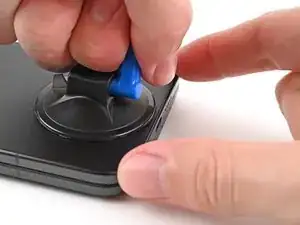
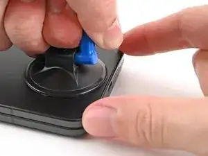
    • Apply a suction cup to the back cover, as close to the center of the bottom edge as possible.

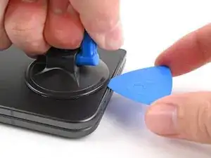
    • While securing the phone with one hand, pull up on the suction cup with strong, steady force to create a gap between the back cover and the frame.

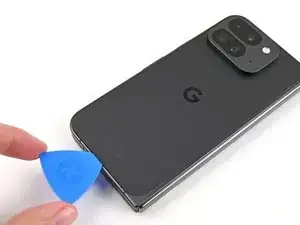
    • Insert an opening pick into the gap.

    • If your back cover is badly cracked, covering it with a layer of clear packing tape may allow the suction cup to adhere. Alternatively, very strong tape may be used instead of the suction cup. If all else fails, you can superglue the suction cup to the broken back cover.

  3. UZvmWmyDaMSKEAPs
    UZvmWmyDaMSKEAPs
    UbqfRkNWj1XfoXq1
    lMZVC6coFycrGEQo
    • During the next two steps, don't insert your opening pick deeper than 3 mm to prevent damaging the metal springs around the frame.

    • Optionally, you can measure and mark your opening pick at 3 mm to help you visualize the length.

    • Remove the suction handle from the back cover.

    • Slide the opening pick around the bottom left corner and up the left edge of the back cover to separate the adhesive.

  4. pjhoqRTyTviaemYo
    pjhoqRTyTviaemYo
    odTUHQI1bdQI1MJA
    ZgVbpDBEdSL42IGC
    • Continue sliding the pick around the top left corner and across the top edge of the back cover.

  5. CaasdZGU4FgOkwDI
    CaasdZGU4FgOkwDI
    rEDGbYqJxGLCJmFt
    qVZJ1RLLExOZsYga
    • The adhesive along the right edge of the back cover is thicker than the rest. You'll need to insert your opening pick at a minimum of 4 mm to separate the adhesive.

    • Slide your pick down the right edge and around the bottom right corner to separate the remaining adhesive.

  6. uBbicSFEuASALPUY
    uBbicSFEuASALPUY
    s1RRIqs6LTZnBgOU
    SgTxtNmkdWrCI1iQ
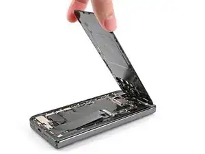
    • Don't fully remove the back cover yet, as it's still connected to the phone by a cable.

    • At this point, the back cover should be free from the frame. If there's still resistance around the edges, use an opening pick to separate any remaining adhesive.

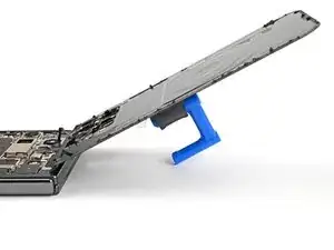
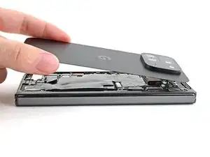
    • Lift the bottom edge of the back cover and swing it over the top edge of the phone.

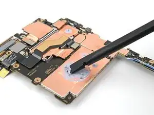
    • Prop up the back cover with your suction handle or a clean, sturdy object—making sure that the cable isn't strained.

  7. hRIxCC1MpvjnQMya
    hRIxCC1MpvjnQMya
    2bspQCbDC5Uenknh
    • Throughout this repair, keep track of each screw and make sure it goes back exactly where it came from.

    • While the Pixel 9 Pro Fold uses Torx Plus screws, standard Torx bits also work. Use the same size or one size larger (T3 or T4 Torx bits with 3IP Torx Plus screws) and apply constant, downward force to prevent stripping.

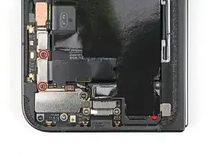
    • Use a Torx Plus 3IP driver to remove the 3.0 mm‑long screw securing the top bracket.

  8. 6KwDVuRmbIsSZ1Bk
    6KwDVuRmbIsSZ1Bk
    1YVsLTrikIxiRuc4
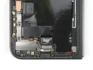
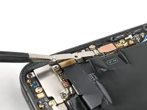
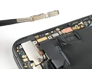
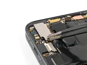
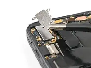
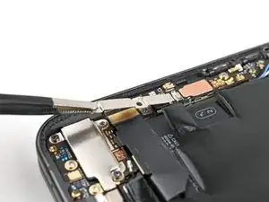
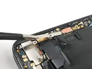
    • Use tweezers, or your fingers, to pull the top bracket towards the top of the phone to release it from its clip.

    • Remove the top bracket.

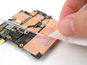
  9. IOpYw6eNxhEimWHF
    IOpYw6eNxhEimWHF
    OLcMQnPbx2RECKET
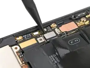
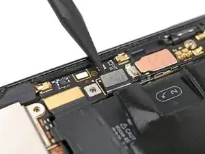
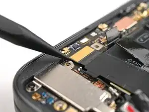
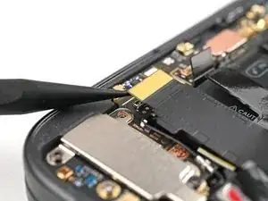
    • Insert the tip of your spudger under the bottom edge of the back cover cable press connector.

    • Don't insert your spudger anywhere else, as you risk dislodging surface‑mounted components.

    • Pry up and disconnect the back cover cable.

  10. iU6uFI1WbWBtRbLb
    • Lift the back cover off the frame and remove it.

  11. c3UDskiawmgL5G3I
    c3UDskiawmgL5G3I
    gMSM1sPyMfIDF4YQ
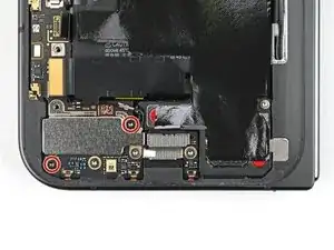
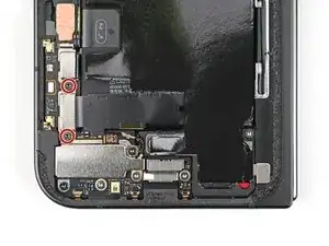
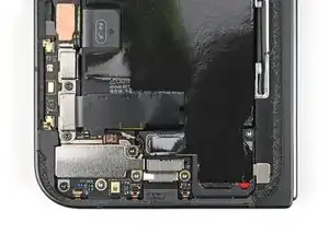
    • Use a Torx Plus 3IP driver to remove the two 3.0 mm‑long screws securing the base battery bracket.

  12. j34hdeHwldj5FF4y
    j34hdeHwldj5FF4y
    A1nO1lZiTSHCvIdF
    T4ofKxcrlWCChvvE
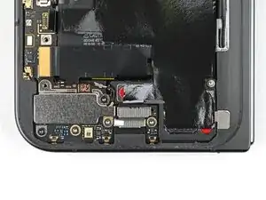
    • Use tweezers, or your fingers, to pull the base battery bracket toward the bottom of the phone to release it from its clip.

    • Remove the base battery bracket.

  13. tVFRWNIFULsbeLUl
    tVFRWNIFULsbeLUl
    wBcNuHnugXQbxMwK
    • Insert the tip of your spudger under the bottom left corner of the base battery press connector, near the gold marker.

    • Don't insert your spudger anywhere else, as you risk dislodging surface‑mounted components.

    • Pry up and disconnect the base battery.

  14. jjbCYqq6YmOsOvSY
    jjbCYqq6YmOsOvSY
    cjmLGQJw2UVipPyL
    • Use a spudger to pry up and disconnect the USB-C port board cable press connector.

  15. KxYfjErbITHhTCqR
    KxYfjErbITHhTCqR
    eWhmmcoKap2ZPcL2
    • Use a Torx Plus 3IP driver to remove the two 3.0 mm‑long screws securing the vibrator bracket.

  16. BbHKTUt6qBucDaDR
    BbHKTUt6qBucDaDR
    CwOCCFUVdOOthWxv
    • Use tweezers, or your fingers, to lift the vibrator bracket off the frame and remove it.

  17. OvkftMhCqAlrxOnX
    OvkftMhCqAlrxOnX
    WC5tGMSIqGksARNX
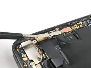
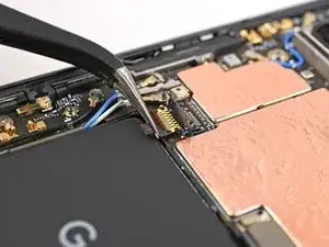
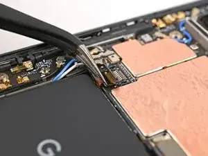
    • Slide one arm of a pair of angled tweezers under the metal neck of the black antenna cable's connector head on the USB‑C board.

    • Lift straight up to disconnect the cable.

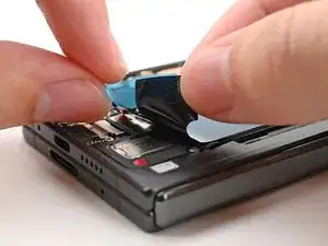
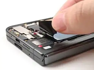
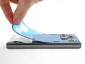
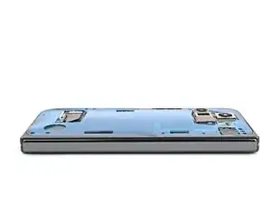
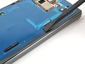
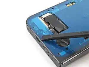
  18. EEV6S1G6s5avKg2Z
    EEV6S1G6s5avKg2Z
    pQdgh1KKmRFFAvGY
    • Use a Torx Plus 3IP driver to remove the two 2.6 mm‑long screws securing the inner front camera bracket.

  19. wO1GwSCHA1GMKQWS
    wO1GwSCHA1GMKQWS
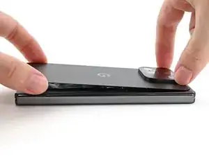
    StTB3NOubJZdshBS
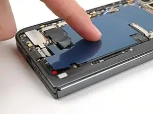
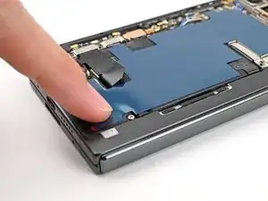
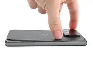
    tQw1QieFAcrXg5rT
    • Use tweezers, or your fingers, to lift the inner front camera bracket up and toward the left edge of the phone to release its clips.

    • Remove the inner front camera bracket.

  20. 6TUMGHIaYiE2xC2m
    6TUMGHIaYiE2xC2m
    IsKrcDjLnjRGEecA
    • Use a spudger to pry up and disconnect the inner front camera press connector.

  21. d1eks1GCoySR4CNg
    d1eks1GCoySR4CNg
    otv4FxFLQnKPiBIT
    tEusGNyayILsHTIT
    • Use the point of a spudger to pry up the inner front camera and separate the adhesive securing it to the frame.

    • Remove the inner front camera.

  22. uPXT6rnjYElJ2owM
    uPXT6rnjYElJ2owM
    eJ2XfmMcqmcCFTax
    TdyYX26srvlm6pgS
    • Slide the flat end of a spudger under the ultra wideband antenna to separate the adhesive foam securing it to the frame.

    • Use tweezers, or your fingers, to lift the antenna off the frame to separate any remaining adhesive.

  23. PgVl6XTZbEO6byyR
    PgVl6XTZbEO6byyR
    rkjoSM1DhPdo2Nvj
    • Use a Torx Plus 3IP driver to remove the two 3.0 mm‑long screws securing the ultra wideband bracket.

  24. 6OMUnOPo5qOOHRrM
    6OMUnOPo5qOOHRrM
    KLOEgFMMqLEJItIp
    V3PblC1DbRUqoNQy
    • While holding the ultra wideband antenna out of the way, pull the bracket toward the bottom of the phone to release its clips.

    • Remove the ultra wideband bracket.

  25. YoGQIlTckihCiPnl
    YoGQIlTckihCiPnl
    pdSU6ufMNdSsr1oe
    • Use a Torx Plus 3IP driver to remove the 3.0 mm‑long screw securing the interconnect cable bracket.

  26. 2JJJSWEGjoBHfKGf
    2JJJSWEGjoBHfKGf
    CsbSrODKVDo6y3MO
    VloFmdqCY15K2fZn
    • Use tweezers, or your fingers, to pull the bracket toward the right edge of the phone to release its clip.

    • Remove the bottom interconnect cable bracket.

  27. EZoIrpRC1iwLEGVJ
    EZoIrpRC1iwLEGVJ
    WyV5p52WUMKmCBpY
    • Use a Torx Plus 3IP driver to remove the 3.0 mm‑long screw securing the inner display cable bracket.

  28. gwjhicJrEiLnSMa3
    gwjhicJrEiLnSMa3
    mho1B1vmIMJcosDU
    • Use tweezers, or your fingers, to pull the inner display cable bracket towards the left edge of the phone to release it from its clip.

    • Remove the inner display cable bracket.

  29. ony3KAJfNcJBwbmC
    ony3KAJfNcJBwbmC
    MUmqLTeeVwGWNZoL
    pXckHap1bJYKJw1X
    • Insert the point of a spudger under the bottom left corner of the inner display press connector, next to the gold marker on the logic board.

    • Don't insert your spudger anywhere else, as you risk dislodging surface‑mounted components.

    • Pry up and disconnect the inner display cable.

  30. PHDgwUJXhlNIppJ1
    PHDgwUJXhlNIppJ1
    c56Iwpm3TpMpwDHd
    NUHUgKTTjmuDTAQK
    • Repeat the previous step to disconnect the top and bottom interconnect cable press connectors, making sure to only pry next to the gold markers.

  31. xgauuMQiwuivsBPM
    xgauuMQiwuivsBPM
    s6tyEaHjlFqCKaFj
    • Peel the graphite sheet off the bottom speaker to separate the adhesive securing it.

  32. 5wCH1LXTQtNSoupP
    5wCH1LXTQtNSoupP
    qqeZKuHvBjFFTvWl
    brvCZNDNIQWBUI46
    • Continue peeling the graphite sheet off the logic board to separate the remaining adhesive.

  33. JSKpMCPKAF3ZZxet
    JSKpMCPKAF3ZZxet
    IIluypQeWBTQGpvL
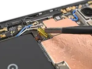
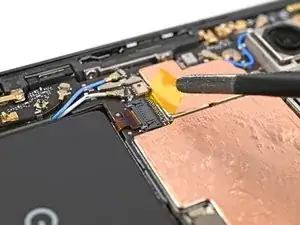
    • Use tweezers, or your fingers, to peel off the yellow tape on the side button cable ZIF connector.

    • Set the tape aside. You'll need it during reassembly.

  34. 5DvRl2dna6ZBZ1rd
    5DvRl2dna6ZBZ1rd
    W1NcMdKoQWU5wbOp
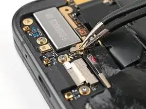
    • Use the point of a spudger, or your fingernail, to lift the locking tab on the side button cable ZIF connector.

  35. MKyJZFKamF461Whg
    MKyJZFKamF461Whg
    iqibbttnfLpPi3al
    • Use angled tweezers to pull the side button cable straight out of its slot.

    • Take care not to puncture the battery—it can leak dangerous chemicals and/or catch fire.

  36. 5bFa5kfIQXqUlrnO
    5bFa5kfIQXqUlrnO
    JfkDRtGR5twVTKQ5
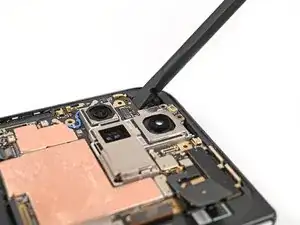
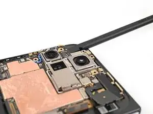
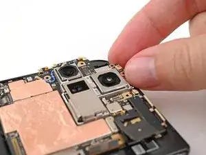
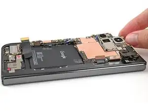
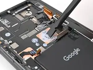
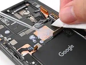
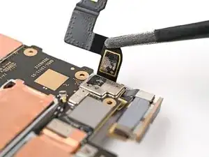
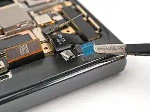
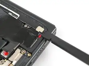
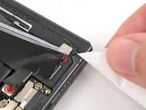
    • A thermal pad lightly adheres the 5G mmWave antenna to the frame.

    • Use the tip of a spudger to pry up the 5G mmWave antenna from the frame and separate it from the thermal pad.

  37. TEoUBKNyUsLn4Ks6
    TEoUBKNyUsLn4Ks6
    bUaXgrbZNF5YmyIE
    • Use a Torx Plus 3IP driver to remove the three screws securing the logic board:

    • One 2.2 mm‑long screw

    • Two 2.6 mm‑long screws

  38. YPRmZRWPNPJ61VBW
    YPRmZRWPNPJ61VBW
    eDsYU3nsJJwWZBEZ
    GsMp5mruIEBfDsSb
    • Insert the flat end of a spudger under the top left corner of the logic board, next to the inner front camera cutout.

    • You might feel some resistance since the logic board is bonded to the frame by thermal paste.

    • Pry up the logic board enough so you can grip the top edge with your fingers.

  39. LkZTftFlDZIaBeAy
    LkZTftFlDZIaBeAy
    DeLGHP3eyMsjKUn3
    OjDrOg5coS5LriPo
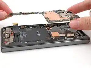
    • Lift the top of the logic board out of the frame and remove it.

    • Lay down the logic board upside down on a clean surface.

  40. XZTwDNDLdkuaNnIG
    XZTwDNDLdkuaNnIG
    A5TW5XopRcvb1DLO
    DmPQRiGFfjKZIGBR
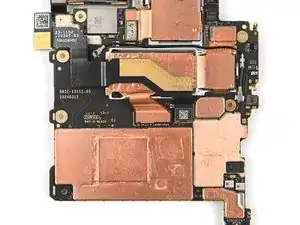
    • Use the flat end of a spudger to scrape away large pieces of old thermal paste from the frame.

    • Apply a few drops of highly-concentrated isopropyl alcohol (over 90%) to any remaining thermal paste residue.

    • Wipe away the residue using a coffee filter or lint-free cloth.

  41. 3S5EFlGVWNtMWuyg
    3S5EFlGVWNtMWuyg
    jT4Q211K5rVaYTSy
    TXGGS5nH3mjOiqCV
    • Don't press down heavily on the logic board while cleaning it to prevent bending the metal springs or smudging the rear camera assembly.

    • Repeat the thermal paste cleaning procedure for the bottom of the logic board.

  42. FSioUjbE5yERKW1C
    FSioUjbE5yERKW1C
    yktVdalKliXltsxf
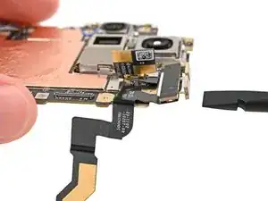
    • Use a spudger to pry up and disconnect the 5G mmWave antenna press connector.

  43. FAjwDCKZrc5duDEk
    FAjwDCKZrc5duDEk
    apmBlaFkNTSUgSiW
    xbs6hR62QTtu2TLi
    • Adhesive secures the 5G mmWave antenna cable on both sides of the logic board.

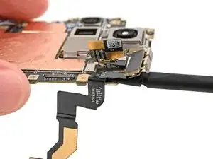
    • Slide the flat end of a spudger under the 5G mmWave antenna cable's adhered section on the bottom of the logic board

    • Pry up the cable to separate the adhesive.

    • Use tweezers, or your fingers, to pull the cable off the logic board and separate any remaining adhesive.

  44. hiLPhWpdM3kgIPFU
    hiLPhWpdM3kgIPFU
    QlPwVqO2UNSGoqoa
    5UKbP2KyRKenAmBK
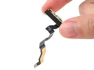
    • Repeat the previous step for the 5G mmWave antenna cable's adhered section on the top of the logic board.

    • Remove the 5G mmWave antenna.

  45. 1ypeAPJTFQejfH1L
    • Congratulations on completing disassembly! The remaining steps will show you how to reassemble your device.

  46. 1DKjM4QtZpXkGmpA
    1DKjM4QtZpXkGmpA
    5ijFdX1DnhLRTVVD
    LMLmITp3kQkRnmIM
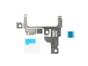
    • Compare your replacement adhesive with your old adhesive. Make sure you have the right adhesive strips.

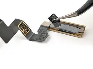
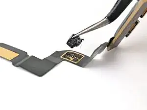
    • Use tweezers, or your fingers, to remove the old adhesive off the 5G mmWave antenna cable and its spots on the logic board.

  47. FaWRX1P6qua4Bwua
    FaWRX1P6qua4Bwua
    eWwjWTQtZaRnKPVN
    XLG2tIZXvmLHAJkw
    • Use isopropyl alcohol (>90% or greater) and a coffee filter or lint‑free cloth to remove any adhesive residue.

  48. WAF6LNYhQcAJqQZm
    WAF6LNYhQcAJqQZm
    lZlcZjsCaq4ECWjn
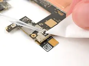
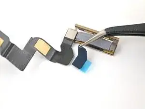
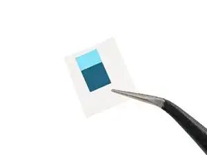
    • Remove the curved adhesive strip from its opaque liner to expose the adhesive underneath.

  49. uDhSRhKdWnxTn2mF
    uDhSRhKdWnxTn2mF
    MNVLkPfXBZTeCYln
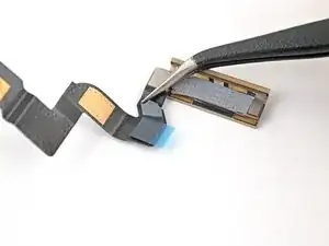
    • Align the curved adhesive strip over the same‑shaped section of the 5G mmWave antenna cable and press it in place.

  50. rflaVmIyASYPqO5u
    rflaVmIyASYPqO5u
    J3FbKkmtFSWYlRZL
    bGZCMrOGguSCZaEN
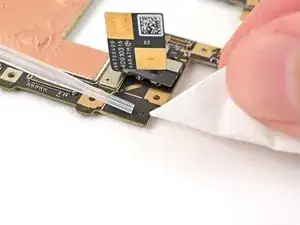
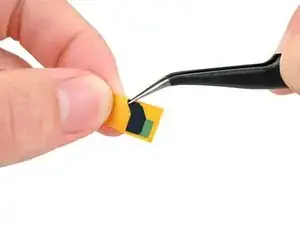
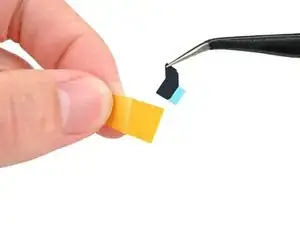
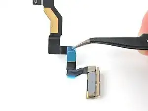
    • Repeat the previous two steps for the square‑shaped adhesive strip, placing it over the gold section on the 5G mmWave antenna cable.

    • Remove the colored liners from both of the adhesive strips to expose the adhesive underneath.

  51. 4nsBgZfoXp6W4yQB
    4nsBgZfoXp6W4yQB
    bYTDgTGSMKxrya5t
    cqhGhWgeRGrZ6IVT
    • Reconnect the 5G mmWave antenna cable.

    • Wrap the cable around its original spot on the logic board and pinch it to re-adhere both sides.

  52. 4BJHHc6aDPI3L5Vx
    4BJHHc6aDPI3L5Vx
    4mGTxbMnMu5hiGhq
    mNHbfHEGrLFGjJG6
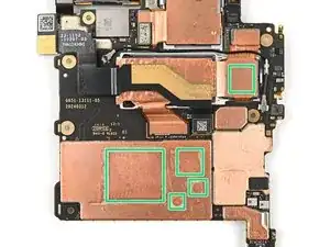
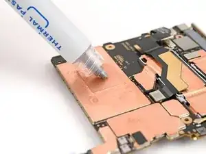
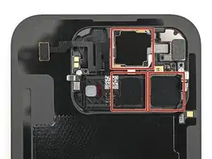
    • Apply small beads of thermal paste (five total) to the motherboard in the same locations as the old thermal paste.

  53. D5UkIxWAIP6ORyaS
    D5UkIxWAIP6ORyaS
    ZGpkRHvpOQYETGRR
    • Place the logic board back into its cutout in the frame, making sure no cables get trapped underneath it.

  54. oRsHNd3bbuE4CwaA
    oRsHNd3bbuE4CwaA
    cNQZvcLb1GNPcEOP
    • Use a Torx Plus 3IP driver to install the three screws securing the logic board:

    • One 2.2 mm‑long screw

    • Two 2.6 mm‑long screws

  55. PyVFGuZeAVlRbMSY
    PyVFGuZeAVlRbMSY
    CKTyTQUqxMErjkb2
    • Use angled tweezers to push the side button cable back into its slot.

  56. sy6vswNn1AglVh5r
    • Flip the locking tab down and lightly press on it until it clicks into place.

  57. cvFasqu1AsSXVNoh
    cvFasqu1AsSXVNoh
    HSg5fQQD3nDUGEYT
    • Place the yellow tape over the ZIF connector and its cable.

  58. W2wvdCkqgWDlcPDS
    W2wvdCkqgWDlcPDS
    FKJuYhmllG41LHcY
    PrA3EJYPPKIAZLEF
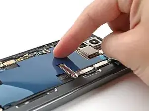
    • Peel the clear liner off your replacement graphite sheet to expose the adhesive on the upper half.

    • Align the upper half of the graphite sheet over the logic board and lay it down.

  59. khVaHCffE1HrPY2E
    khVaHCffE1HrPY2E
    QEjJEuOvwsaYLQhR
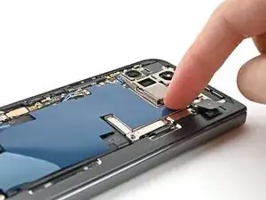
    • Use your finger to press down the upper half of the graphite sheet and secure it to the logic board.

  60. TfuRWQT3GnaZ4rcf
    TfuRWQT3GnaZ4rcf
    vQV5FCoH4GXYNbf5
    • Remove the blue liner from the bottom of the graphite sheet to expose the adhesive underneath.

  61. Ocio3lye1dkdAPn1
    Ocio3lye1dkdAPn1
    GPYpIXBqniArxyMN
    cUxcinENnuchJhaL
    • Drag your finger from the middle section of the graphite sheet to the adhesive spot on the loudspeaker to flatten the graphite sheet and adhere it.

  62. LyZbGPRfw1uIJF4q
    LyZbGPRfw1uIJF4q
    ULskAUpTNpHcnQEE
    3BygDPVDSVowQDFS
    • Grip the pull tab at the top of the graphite sheet and peel off the remaining liner.

  63. IJZUQR4fRJDuoNIW
    IJZUQR4fRJDuoNIW
    ASSncFASdkTqHpHh
    rxoWxEyxwQSxfAmO
    • Reconnect the inner display cable and the top and bottom interconnect cable press connectors.

  64. EjJUvPUqX2SaCoUB
    EjJUvPUqX2SaCoUB
    QwEmSPYFM4DElMPu
    • Reinsert the inner display cable bracket clip under its slot in the logic board and align the screw holes.

  65. vhV3fvPHVkKADkfF
    vhV3fvPHVkKADkfF
    5NBmLW2StcRhEkdU
    • Use a Torx Plus 3IP driver to install the 3.0 mm‑long screw securing the inner display cable bracket.

  66. mU1nnUQPa1JhdaV6
    mU1nnUQPa1JhdaV6
    pn6dlkvByaLNCxBh
    • Reinsert the bottom interconnect bracket clip under its slot in the frame and align the screw hole.

  67. wSGpJJgt1Q32a6qn
    wSGpJJgt1Q32a6qn
    KqdikeBUbTESsq2Y
    • Use a Torx Plus 3IP driver to install the 3.0 mm‑long screw securing the interconnect cable bracket.

  68. Xnv3TWo3PCEBbu5l
    Xnv3TWo3PCEBbu5l
    OKDu3WYjxYkytFbD
    • While holding the ultra wideband antenna out of the way, reinsert the ultra wideband bracket clip under its slot in the frame and align the screw holes.

  69. WfgeCbDpXOndvKcW
    WfgeCbDpXOndvKcW
    2GPJmyrUg3oXtFZU
    • Use a Torx Plus 3IP driver to install the two 3.0 mm‑long screws securing the ultra wideband bracket.

  70. p6KpHtR5IGuGILaC
    p6KpHtR5IGuGILaC
    GxDrPclvfpiPNoYO
    ISZEpHrq1xIKMWAV
    • If the adhesive on your ultra wideband bracket is still sticky, skip this step.

    • Remove the old adhesive and foam on the ultra wideband bracket and under the antenna.

    • Replace the corresponding adhesive and foam to the bracket and the frame.

    • Press the ultra wideband antenna to the frame and re‑adhere it.

  71. rVlgOIHkirtnqrFd
    rVlgOIHkirtnqrFd
    TjvgxrXZaAOOJURj
    KfCWXO2Tn1jAgIlv
    • Use tweezers, or your fingers, to remove the old adhesive foam from the inner front camera cutout.

    • Use isopropyl alcohol (>90% or greater) and a coffee filter or lint‑free cloth to remove any adhesive residue.

  72. PRnHOGLEdZ4apOrR
    PRnHOGLEdZ4apOrR
    U2Ukd6oh2J6qVGQy
    KZh1DVSTHfbNJT3S
    • Peel the replacement inner front camera adhesive foam off its clear liner to expose the adhesive underneath.

    • Align the adhesive foam over the cutout in the frame so that the pull tab is facing the bottom of the phone.

    • Place the adhesive in the cutout.

  73. MrA2ZBOtS1IhjCaL
    MrA2ZBOtS1IhjCaL
    MlRjmwrlGKcCSRXa
    jvcaMT15FtUwodO2
    • Use the tip of a spudger to press along the edges of the adhesive foam to secure it to the frame.

  74. q6PY2qWVA4JqwgMK
    q6PY2qWVA4JqwgMK
    bnq4GcU3GYdlIDsG
    K1BRUaIVTvujmbQv
    • Use tweezers, or your fingers, to peel off the colored liner and expose the adhesive underneath.

  75. jrnlIacQCi2c5R12
    jrnlIacQCi2c5R12
    3swfHiZSqKRHObjY
    • While holding the inner front camera above its cutout, reconnect its press connector.

    • Lay the inner front camera in its cutout and press down to secure it to the adhesive.

  76. Eadjw4ZTAWL6mfaC
    Eadjw4ZTAWL6mfaC
    3HNFPrdmXjSlfJM4
    AyblZpVrOnmKfxuR
    • Reinsert the inner front camera bracket clip under its slot in the logic board and align the screw holes.

  77. mvcCByAahrG2MDpT
    mvcCByAahrG2MDpT
    kyFNDdbyiVmByxls
    • Use a Torx Plus 3IP driver to install the two 2.6 mm‑long screws securing the inner front camera bracket.

  78. t43dXbSdVOBvq6qD
    • Use tweezers to hold the antenna cable's connector in place over its socket and gently press down with your finger or a spudger until the connector snaps into place.

  79. vHGxAbYWOX4SEUZx
    vHGxAbYWOX4SEUZx
    VYBchXPMo1rgPuXV
    • Place the vibrator bracket on the logic board and align its screw holes.

  80. RKdDJXZorMfkBWKu
    RKdDJXZorMfkBWKu
    ukAZYxQqSAjGUNLC
    • Use a Torx Plus 3IP driver to install the two 3.0 mm‑long screws securing the vibrator bracket.

  81. lE4CZSShWkALbBsl
    • Reconnect the USB-C port board cable press connector.

  82. dmxiCvDiEpUCCcJU
    • Reconnect the base battery press connector.

  83. fpSxsPYdHf32uhnG
    fpSxsPYdHf32uhnG
    kSt1WguA5A6PTKlF
    • Reinsert the base battery bracket clip under its slot in the logic board and align its screw holes.

  84. QAEUPePNdLGdWpdg
    QAEUPePNdLGdWpdg
    YKJveO3H6nP1wVed
    • Use a Torx Plus 3IP driver to install the two 3.0 mm‑long screws securing the base battery bracket.

  85. eCap2YTpUhpSi66E
    eCap2YTpUhpSi66E
    C12Py5hmQwAQ5IAG
    • Use a spudger, or your fingers, to remove the old back cover adhesive.

    • Use isopropyl alcohol (>90%) and a coffee filter or a microfiber cloth to remove any adhesive residue.

  86. Amdw2XL4ZEfcfKHZ
    Amdw2XL4ZEfcfKHZ
    4Ab4IMaiCeICPVFd
    15qQZbOeByXhk5sW
    • If you're replacing your back cover with a new one, follow the next two steps. Otherwise, skip them.

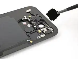
    • Use tweezers, or your fingers, to remove the three rear camera liners from the inside of your new back cover.

  87. Yc4JEP5WADWulQW5
    Yc4JEP5WADWulQW5
    D6eMD4SIOs6QdWPY
    U5gFPxMHulJ4qhAJ
    • Peel off the remaining clear liners on the outside of the back cover.

  88. nbYLNcwbVGPgehij
    nbYLNcwbVGPgehij
    MKP4rgXD2pYCv6Fh
    • Before removing any liners, check if the adhesive matches the frame.

    • The clear liner should face the frame.

  89. cMOGGwRMbVBkyhmy
    cMOGGwRMbVBkyhmy
    auENNTE5cGO6m5GE
    WAQPLQTWxXSQVvxU
    • Be careful during this step, as it's easy to stick the adhesive in the wrong spot. Take your time and work slowly.

    • Peel away the top half of the new adhesive strip from its clear liner and keep it folded before continuing.

    • Align the top half of the adhesive over the frame, using the corners as reference points.

    • Place the adhesive on the frame.

  90. 5rvU26L4UaQ5trTQ
    5rvU26L4UaQ5trTQ
    XwnlolWAuWqdEvAL
    • Use the flat end of a spudger, or your fingers, to press down the top edge of the adhesive and adhere it to the frame.

  91. ZrysmKXcIyy6wEcy
    ZrysmKXcIyy6wEcy
    ePoUCRfKufZkq51g
    vJP5jvjPkhPQOMTu
    • While peeling away the rest of the clear liner, slowly lay the rest of the adhesive over the perimeter of the phone.

  92. 6QhACV4eVGNlOfMr
    6QhACV4eVGNlOfMr
    Qygy2NnNLHy4JQOD
    oeRPtfbsrdA2KyFW
    • Use the flat end of a spudger, or your fingers, to press down the rest of the adhesive and adhere it to the frame.

  93. 1DOUqlXqgOsx4WeB
    1DOUqlXqgOsx4WeB
    lSWJFlWZoRtWbjAR
    tsICW3jTnt4alYRX
    • Use a spudger to pry up the segmented tab on the bottom right corner of the large blue liner.

    • Lift the tab and peel off the large blue liner to expose the secondary liner.

    • If any of the adhesive starts to peel up with the liner, gently lay it back on the frame and use the flat end of a spudger to secure it.

  94. QVwTYuQtasMCQ2vQ
    • While holding the back cover or propping it up, reconnect the back cover cable.

    • Don't try to force the connector into place. If you're having trouble, reposition it and try again.

  95. VpiWldhRbTb2PZvD
    VpiWldhRbTb2PZvD
    EVWwH45LSBoqjmVg
    • Reinsert the top bracket clip under its slot in the logic board and align its screw hole.

  96. RnqToNSZIbsCFsfn
    RnqToNSZIbsCFsfn
    NVh6wnmmj3KULqgM
    • Use a Torx Plus 3IP driver to install the 3.0 mm‑long screw securing the top bracket.

  97. xI6NLM4hLaAOorGk
    xI6NLM4hLaAOorGk
    3TsXoVhQ2aEUNEGR
    • Use the tip of a spudger to pry up the segmented tab on the top right corner of the secondary liner.

  98. 3nUv2cItwmANAiQc
    3nUv2cItwmANAiQc
    jJxokA61LqZhJjdk
    PxQAtntJCmeMXSuX
    • Peel off the secondary liner to expose the adhesive.

    • If any of the adhesive starts to peel up with the liner, gently lay it back on the frame and use the flat end of a spudger to secure it.

  99. bPCuheP5yFqca2CS
    bPCuheP5yFqca2CS
    qfGEReeEJg4PDwyC
    • Align the top edge of the back cover with the frame and press down to adhere it.

  100. qAhlP2CnOjlg4Orr
    qAhlP2CnOjlg4Orr
    a5iKTUfOYr4SMAVh
    LYuVXCkvDeWtIdpQ
    • Press along the perimeter of the back cover to adhere it to the frame.

    • Optionally, you can use a hair dryer or heat gun to lightly heat the edges of the back cover and create a stronger bond.

    • Let the phone sit a few hours for the adhesive to cure.

Conclusion

Congratulations on completing your repair!

Take your e-waste to an R2 or e-Stewards certified recycler.

Repair didn’t go as planned? Try some basic troubleshooting, or ask our Google Pixel 9 Pro Fold Answers Community for help.
Alex Diaz-Kokaisl

Member since: 16/01/22

151892 Reputation

0 comments