Introduction
This repair guide was authored by the iFixit staff and hasn’t been endorsed by Google. Learn more about our repair guides here.
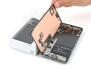
Follow this guide to replace the logic board in your Google Pixel 8 Pro.
Replacing the logic board requires removing the battery, which is a difficult process. If the battery gets bent, creased, or damaged during removal, you'll need to replace it.
You'll need replacement screen adhesive to complete this repair.
Note: This guide was made with the 5G mmWave antenna model of the Pixel 8 Pro. If you have the non-mmWave version, you can still use this guide—just skip the steps that mention the 5G mmWave antenna.
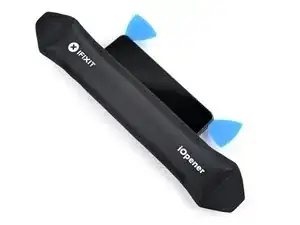
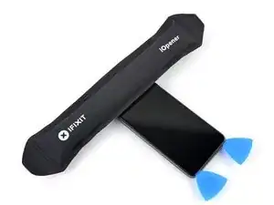
Tools
-
-
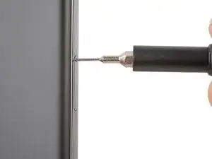
Firmly press a SIM eject tool, bit, or straightened paper clip into the SIM card tray hole on the left edge of your phone until the tray ejects.
-
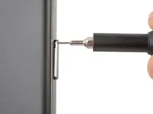
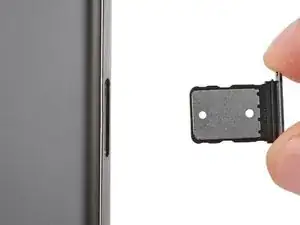
Remove the SIM card tray.
-
-
-
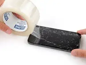
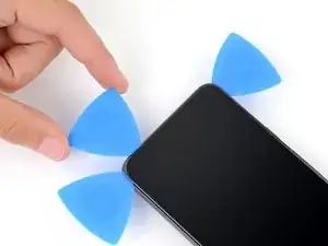
Apply overlapping strips of packing tape to the cracked glass until the whole screen is covered.
-
Wear safety glasses to protect your eyes from any glass shaken free during the repair.
-
-
-
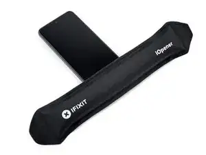
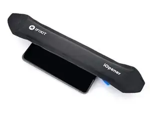
Heat an iOpener and lay it on the bottom edge of the screen for two minutes to soften the adhesive.
-
-
-
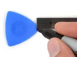
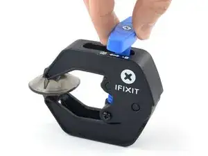
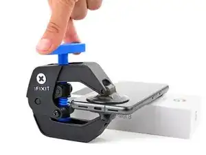
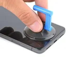
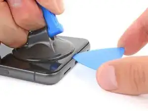
Pull the blue handle backwards to unlock the Anti-Clamp's arms.
-
Place your phone screen side up on an object so it will rest level between the Anti-Clamp's arms—the bottom edge should be hanging off.
-
Slide the arms over the left edge of your phone, so you have access to the bottom edge.
-
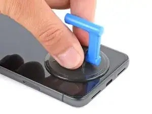
Position the suction cups as close to the center of the bottom edge as possible.
-
Squeeze the cups together to create suction.
-
-
-
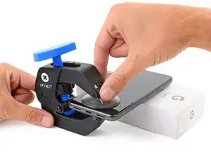
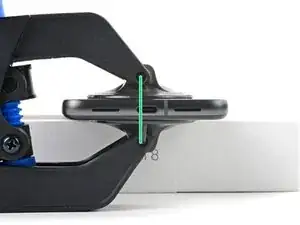
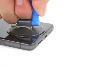
Pull the handle forward to lock the arms.
-
Turn the handle clockwise one full turn (360 degrees), or until the suction cups begin to stretch.
-
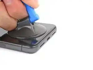
As the cups stretch, make sure they stay aligned with each other. If they keep slipping, remove the Anti-Clamp and apply tape for the cups to stick to.
-
-
-
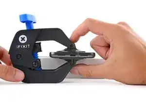
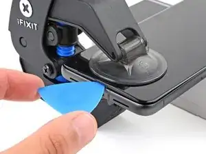
Wait one minute for a gap to form between the screen and frame.
-
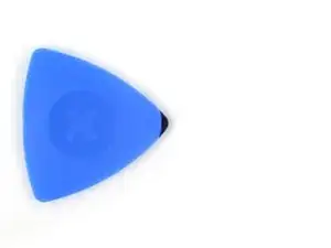
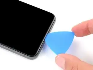
Insert an opening pick into the gap.
-
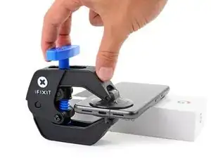
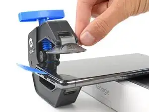
Pull the blue handle backwards to unlock the arms and remove the Anti-Clamp using the pull tabs on the suction cups.
-
Skip the next two steps.
-
-
-
Pull up on the suction handle with strong, steady force until a gap forms between the screen and frame.
-
Insert an opening pick into the gap.
-
-
-
The screen cable is a little less than halfway up the left edge of the phone. Be very careful here to avoid tearing the cable.
-
There are many spring contacts around the perimeter of the phone. Be very careful in these areas to avoid bending the contacts.
-
-
-
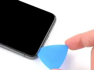
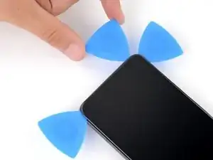
Slide the opening pick along the bottom edge to separate the adhesive securing it.
-
Leave the pick in the bottom right corner to prevent the adhesive from resealing.
-
-
-
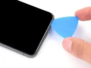
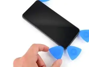
Insert a second opening pick under the bottom right corner of the screen.
-
Slide the new pick to the top right corner to separate the adhesive securing the screen's right edge.
-
Leave the pick in the top right corner to prevent the adhesive from resealing.
-
-
-
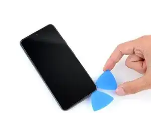
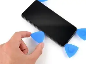
Insert a third opening pick under the bottom edge of the screen.
-
Slide the new pick to the bottom left corner.
-
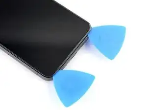
Leave the pick in the bottom left corner to prevent the adhesive from resealing.
-
-
-
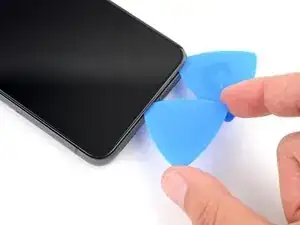
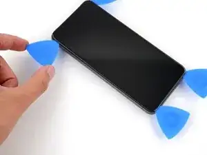
Insert a fourth opening pick under the bottom left corner of the screen.
-
Slide the new pick to the top left corner to separate the adhesive securing the screen's left edge.
-
Leave the pick in the top left corner to prevent the adhesive from resealing.
-
-
-
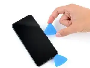
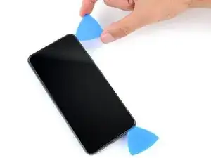
Insert a fifth opening pick under the top edge of the screen, near the left corner.
-
Slide the opening pick to the top right corner to separate the adhesive securing the screen's top edge.
-
-
-
Place a small box or stack of books to the left of your phone so you can prop up the screen while disconnecting its cable.
-
Swing up the right edge of the screen like the front cover of a book.
-
Prop up the screen so you can access the screen cable without straining it.
-
-
-
Insert the point of a spudger under the top right corner of the screen's press connector.
-
Gently pry up and disconnect the cable.
-
Remove the screen.
-
-
-
Use the pull tabs to remove the liners covering the front camera cutout, the back of the screen, and the perimeter adhesive.
-
Reconnect the screen cable and reinstall its cover.
-
This is a good point to test your phone before sealing it up. Temporarily power on your phone and make sure it works as expected. Power it down before continuing.
-
Firmly press the screen into place on the frame—you should feel the clips "pop" into place.
-
Press firmly around the perimeter of the screen to secure it with the new adhesive.
-
Follow this guide to calibrate the fingerprint sensor.
-
-
-
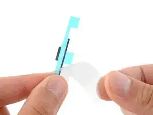
Insert the tip of a spudger under the top edge of the 5G mmWave antenna's press connector.
-
Gently pry up and disconnect the cable.
-
-
-
Heat an iOpener and lay it on the 5G mmWave antenna cable for two minutes to soften the adhesive.
-
-
-
Insert the flat end of a spudger between the bottom of the 5G mmWave antenna cable and the midframe, just above the press connector.
-
Twist the spudger to separate the bottom of the cable from the midframe.
-
-
-
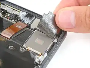
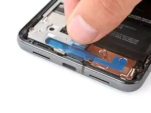
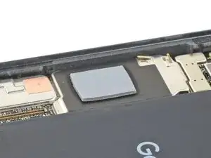
Insert the point of a spudger under different parts of the graphite sheet and lift until you can grip the sheet with your fingers.
-
Peel up and remove the entire graphite sheet.
-
-
-
Use the tip of a spudger to gently lift the plastic shim that runs along the top of the USB-C port cover.
-
Remove the shim and set it aside or move it out of the way so you can access the USB-C port cover screws.
-
-
-
Remove the larger rectangular liner from the shim.
-
Place the shim so the smaller piece of foam lines up with the bottom of the USB-C port cover.
-
Use the flat end of a spudger to firmly press down along the whole shim to secure it.
-
Remove the remaining liner.
-
-
-
Use a T3 Torx screwdriver to remove the two 5 mm‑long 3IP Torx Plus screws securing the USB‑C port cover.
-
Remove the cover.
-
-
-
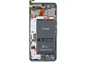
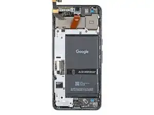
Use a T3 Torx screwdriver to remove the seven 5 mm‑long 3IP Torx Plus screws securing the midframe.
-
-
-
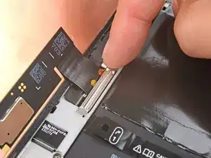
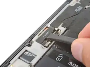
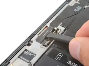
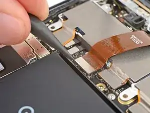
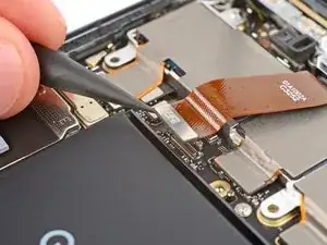
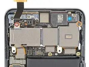
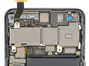
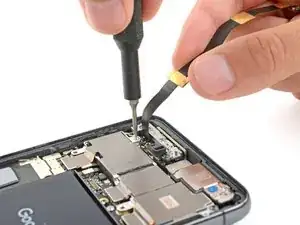
Use the point of a spudger to pry up and disconnect all three rear camera press connectors from the top edge of the logic board.
-
-
-
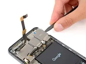
Use a T3 Torx screwdriver to remove the two screws securing the rear camera assembly:
-
One 3.5 mm‑long 3IP Torx Plus screw securing the top left corner
-
One 5 mm‑long 3IP Torx Plus screw securing the top right corner
-
-
-
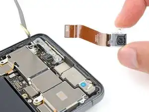
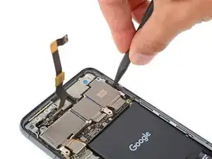
Insert a spudger between the right edge of the rear camera assembly and frame.
-
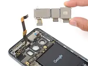
Pry the rear camera assembly up and remove it.
-
-
-
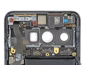
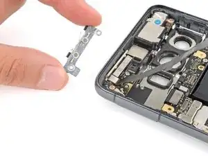
Use a T3 Torx screwdriver to remove the two 5 mm‑long 3IP Torx Plus screws securing the 5G mmWave antenna bracket.
-
-
-
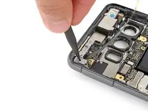
Insert the tip of a spudger in one of the 5G mmWave antenna bracket's screw holes.
-
Pry up with the spudger to dislodge the bracket.
-
Remove the bracket.
-
-
-
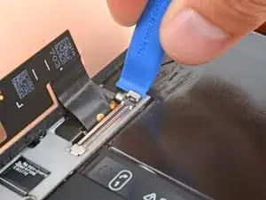
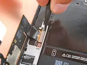
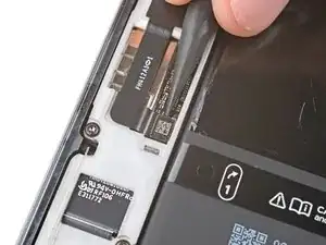
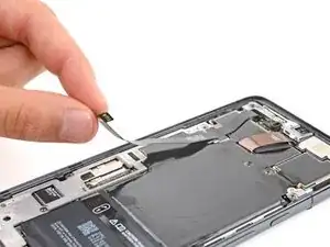
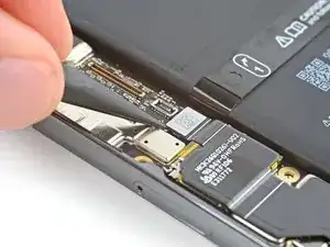
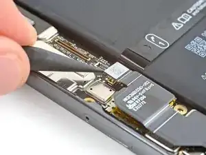
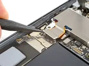
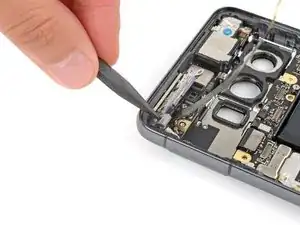
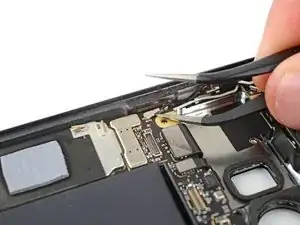
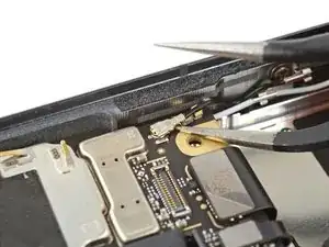
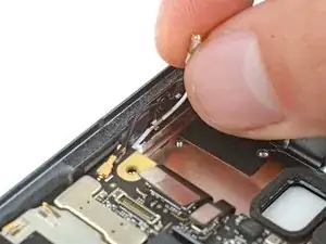
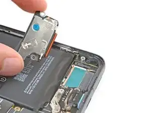
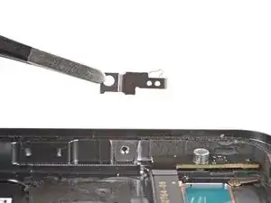
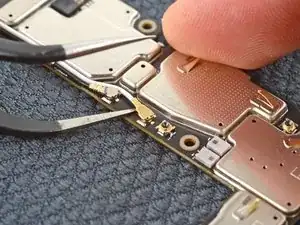
Insert one arm of a pair of angled tweezers under the metal neck of the black antenna cable coaxial connector, located on the top left corner of the logic board.
-
Gently lift straight up to disconnect the cable.
-
-
-
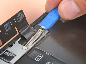
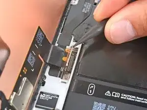
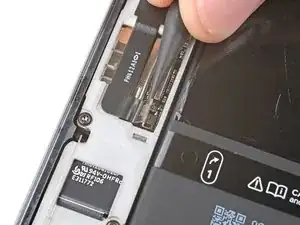
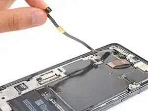
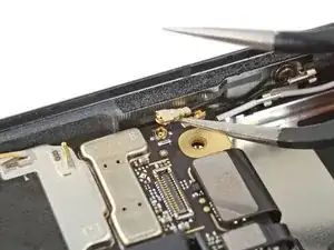
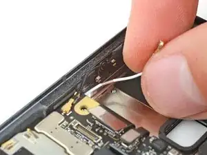
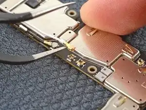
Insert one arm of a pair of angled tweezers under the metal neck of the white antenna cable coaxial connector, located on the top left corner of your phone.
-
Gently lift straight up to disconnect the cable.
-
-
-
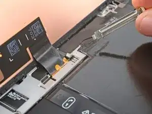
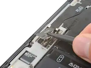
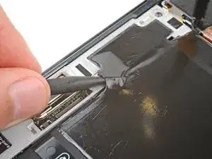
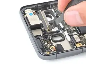
Use the point of a spudger to pry up and disconnect the interconnect and ultra-wideband press connectors from the top left corner of the logic board.
-
-
-
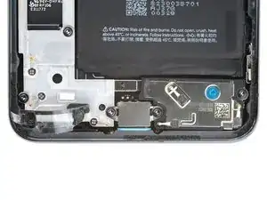
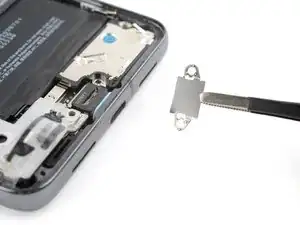
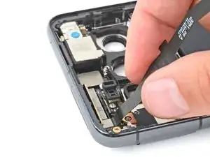
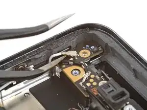
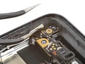
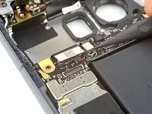
Use a T3 Torx screwdriver to remove the 5 mm‑long 3IP Torx Plus screw securing the loudspeaker.
-
-
-
Insert the point of a spudger between the bottom right edge of the loudspeaker and frame.
-
Pry the loudspeaker up with the spudger to dislodge it from its recess.
-
Remove the loudspeaker.
-
-
-
Flip your phone back over and lay it on your workspace.
-
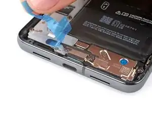
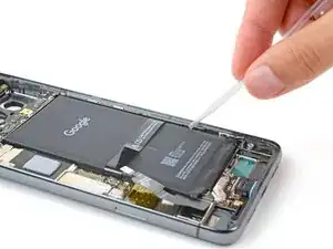
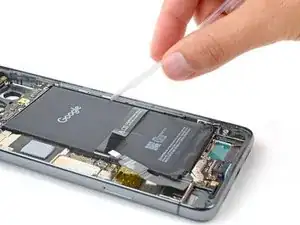
Apply a few drops of highly-concentrated isopropyl alcohol along the right edge of the battery.
-
Tilt your phone to help the alcohol flow towards the adhesive on the top and bottom edges of the battery.
-
Wait one minute to allow the alcohol to dissolve the adhesive.
-
-
-
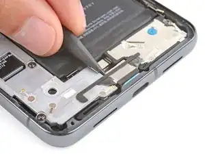
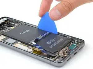
Firmly secure your phone with one hand.
-
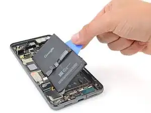
With your free hand, pry the battery up with the pick. Maintain constant pressure on the pick until the battery separates from the frame.
-
-
-
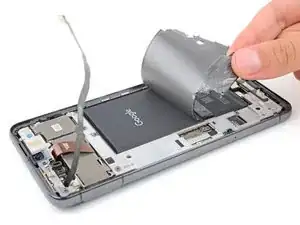
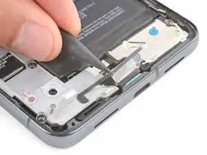
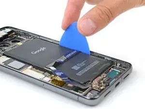
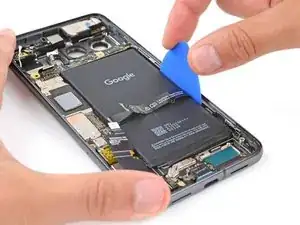
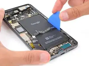
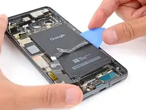
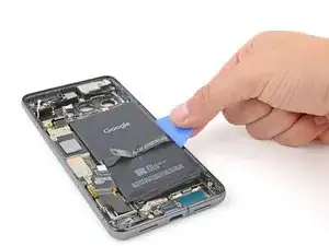
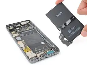
Use the opening pick to lift the battery and separate the remaining adhesive.
-
Remove the battery.
-
Follow this guide to remove the old adhesive and install your battery.
-
-
-
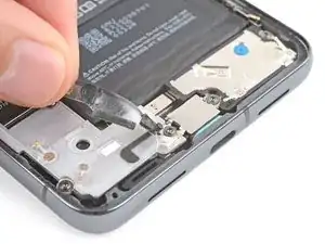
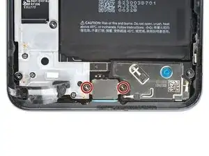
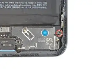
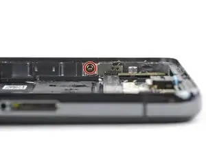
Use a T3 Torx screwdriver to remove the 2.5 mm‑long 3IP Torx Plus screw securing the grounding bracket to the bottom right edge of your phone.
-
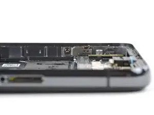
Remove the grounding bracket.
-
-
-
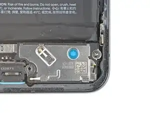
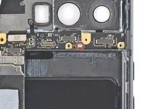
Use a T3 Torx screwdriver to remove the 3.5 mm‑long 3IP Torx Plus screw securing the logic board.
-
-
-
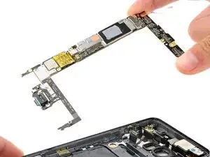
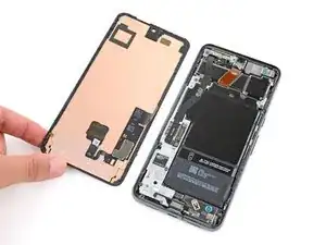
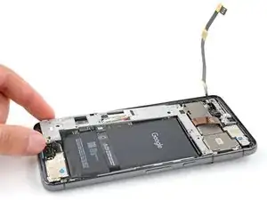
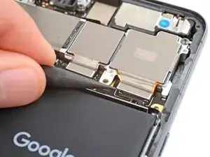
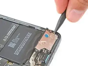
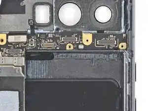
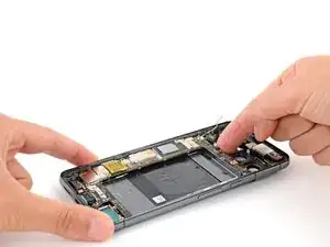
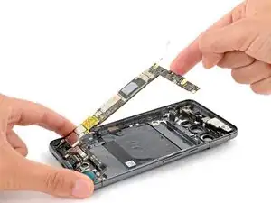
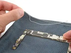
Lift the top edge of the logic board and remove it, making sure no cables get snagged on the board.
-
Make sure the interconnect, ultra-wideband, and black antenna cables are out of the way before putting the board into place.
-
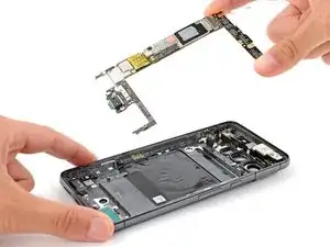
Insert the board at a downward angle so the USB‑C port goes into its recess in the bottom of the frame.
-
Lay the top of the board down and push it into its recess.
-
-
-
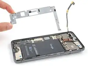
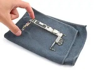
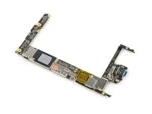
Flip the logic board over and lay it down on a soft, clean surface such as a towel to prevent damaging it.
-
-
-
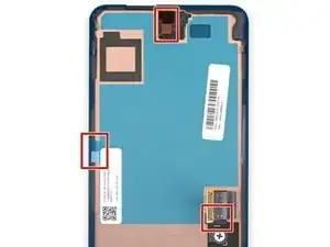
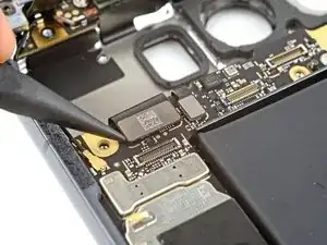
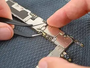
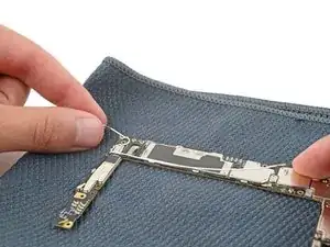
Insert one arm of a pair of angled tweezers under the metal neck of the white antenna cable coaxial connector, located on the bottom of the logic board.
-
Gently lift straight up to disconnect the cable.
-
-
-
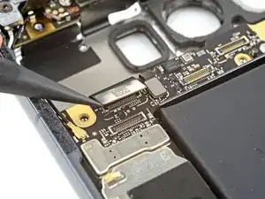
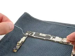
Gently pull the white antenna cable out of its clips on the bottom of the logic board.
-
Remove the antenna cable.
-


To reassemble your device, follow these instructions in reverse order.
To run a diagnostics test with the built-in Pixel Diagnostic tool, click here.
Take your e-waste to an R2 or e-Stewards certified recycler.
Repair didn’t go as planned? Try some basic troubleshooting, or ask our Answers community for help.

3 comments
I need an unlocked pixel 8 pro logic board where can I get one? Thank you so much Brian Purvis
brianpurvis5@gmail.com
Hi, I can't see 5g antenna and cable in my 8 pro. Is it a common thing? Does it mean the 5g is built-in the T3 CPU? Please advise. Many thanks in advance.
MSP -
Hi! It's possible you don't have the mmWave version of the Pixel 8 Pro. As the introduction and step 24 state, you can still use this guide if you have the non-mmWave version, just skip the steps mentioning the mmWave antenna and cable.