Introduction
This repair guide actually focuses more on determining HOW to fix when we don't know all the details. You will learn how to figure out which is the correct power lead when all you have is a generic power brick and an ambiguous 3-prong power plug.
-
-
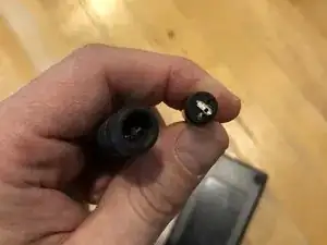
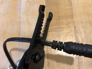
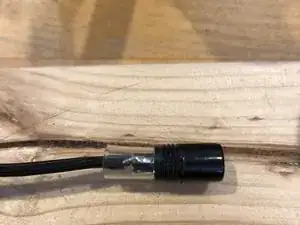
The problem is that there are 2 wires and 3 leads on the power connector, so which ones get connected, and which is the right wire?
-
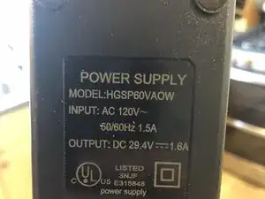
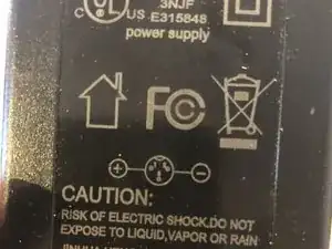
We can look at the power brick and see that 1) it signifies that it's 29.4 Volts DC and 2) the + goes to lead #1 and the - goes to lead #2 (and that pin #3 is unused.
-
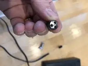
The convention for this image is that the reader is looking at the plug head-on.
-
-
-
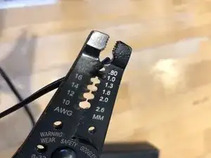
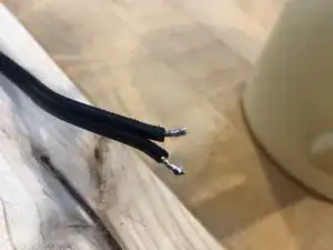
Cut off the old power plug, strip and tin the ends of the wire. There should be just a few mm of tinned wire showing.
-
-
-
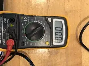
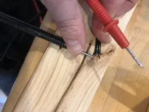
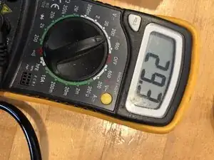
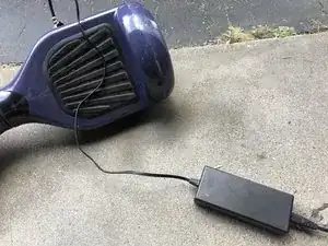
Plug in the power adapter ensuring that the two leads do not touch. Attach the multimeter to leads. Basically if it shows the correct voltage as a positive value, the orientation of + and - is correct. If the multimeter reads a negative value, you have the polarity incorrect.
-
Once you have figured out the correct + and -, make a note of which is which. You can put a dab of red nailpolish on the + wire.
-
Remember that the voltage is 29.4VDC. You have to set your multimeter correctly. See that I set mine to the 200V range - because the 20V range would be too low.
-
-
-
In step two, we see that the power brick says the orientation of the polarity vis a vis the plug. The perspective is from looking at the plug. So #1 (the top left) is +, and #2 (the top right) is -. The bottom lead - is unused.
-
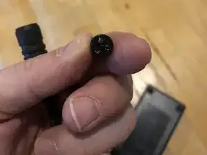
Look closely at the plug and you'll see the orientation is labeled. So you will solder the two leads onto the other side.
-
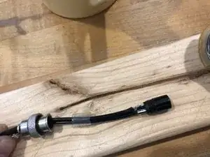
Remember to slide the metal casing, followed by the clear jacket over the wire first before you solder on the plug.
-
As planned, solder + (you might have marked this red with nail polish) to #1, and the other lead to #2.
-
-
-
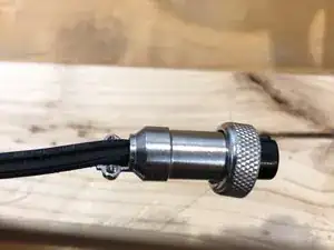
Screw the jacket around the plug.
-
Screw in the end-collar to hold the jacket on the wire.
-
After reapplying power, Test by putting the two multimeter probes into the correct leads. You see in this image that red is touching the top left, and black is touching the top right. As expected we see positive 29.4 volts. This is a good test and we are done.
-


To reassemble your device, follow these instructions in reverse order.