Introduction

  1. CYoAQnAVcTIMQDn1
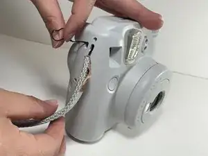
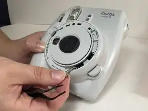
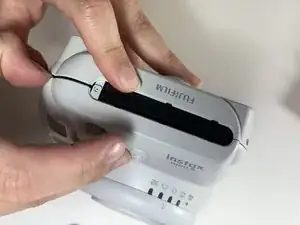
    • Untie the wrist strap by loosening the small black end of it, and pulling the large part out of the loop it makes which holds it in place.

  2. DSmmnVgoYXfx2R6d
    DSmmnVgoYXfx2R6d
    BFGFUKvp3inHMvpY
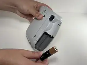
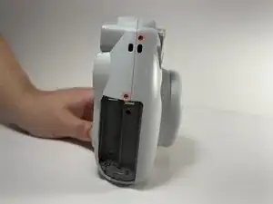
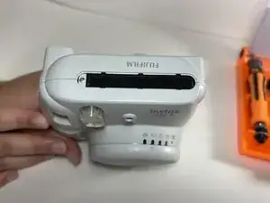
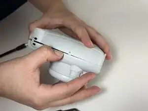
    • Turn the camera on its side and take off the battery cover by pulling down while putting pressure onto the cover.

    • Remove both AA batteries.

  3. VhIEWfB5VOtBBI5p
    VhIEWfB5VOtBBI5p
    yQOborQRRXnu3Mri
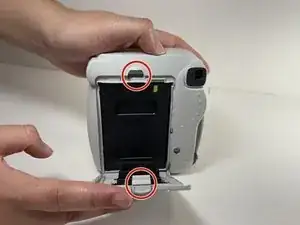
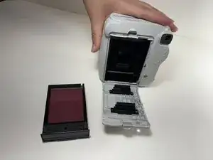
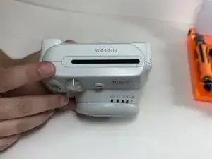
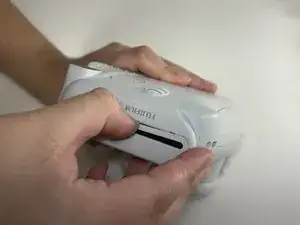
    • Turn the camera to its back side and push down on the clip at the top of the film cover and remove film.

  4. m5AxeCFDAchjdIFC
    m5AxeCFDAchjdIFC
    1SI4GVmfEnOGMCuE
    sTl4Nxf2UjEeuleq
    • Remove the six shell screws highlighted using a Philips #00 screwdriver.

  5. vFAARwmTgH1LZSYx
    vFAARwmTgH1LZSYx
    6KUrM5Ps1BFYUufO
    ubUMSgKiV3UL2MRq
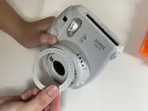
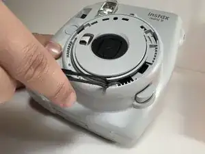
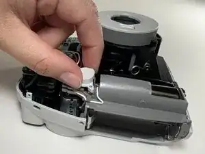
    • Remove the shroud for the film printer. Carefully pry around the edge of the shroud until the part comes loose.

  6. T5XSGp5iYWJxXMdW
    T5XSGp5iYWJxXMdW
    bOHZtVpNg2SHlQHJ
    • Carefully pry around the lens shroud in a circular motion in order to remove it.

  7. ZmJIdrwSUmQ1aGIM
    ZmJIdrwSUmQ1aGIM
    o5ZceYHtZfunBjAD
    • Unhook the spring attached to the lens.

  8. RejRIAgrjFJEZuoE
    RejRIAgrjFJEZuoE
    6ZNHOQBwMDfDGRVa
    qXDeJORUQ5myvsrE
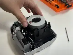
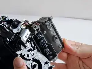
    • Gently pry along the shell seam while tracing the seam along all sides of the camera. Take the front shell off the camera once the shell is released.

  9. frEXWsYFW1OJAWn1
    • Take the button that controls the shutter off of the camera.

  10. SPpDuKUR6aWFKpWD
    SPpDuKUR6aWFKpWD
    K1pmiHBO4XCTTJwt
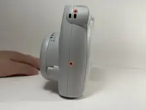
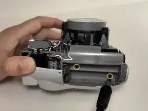
    • Remove the battery slot by unscrewing the two highlighted screws. Once loose, remove the piece to reveal the capacitor.

    • Note: These two screws are smaller than the case screws removed earlier.

  11. PR6VjBLR4KyqJCVA
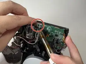
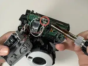
    • Heat the soldering iron up to 600°F and firmly hold it onto the soldered contacts.

    • Replace the flash capacitor by de-soldering the highlighted contacts.

    • Use a soldering wick or a vacuum pump to absorb the melted solder and remove capacitor once the wires are separated from the contacts.

    • Note: The capacitor is rated for 320V and has a capacitance of 300µF

  12. GThMaqjZORLabrZI
    • Solder the two white wires back into place.

Conclusion

To reassemble your device, follow these instructions in reverse order.

g124um

Member since: 14/11/24

223 Reputation

0 comments