Introduction
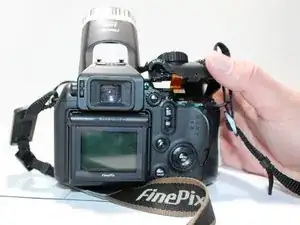
This is a guide for removing the back case of the Fujifilm FinePix S9500 camera. The back case is responsible for protecting the delicate electronics housed within. This guide will also show you how to remove the case top.
Tools
-
-
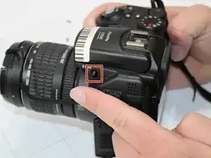
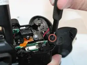
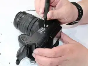
Locate and remove two screws. They are M1.7 x 5.0 in size.
-
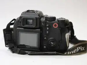
The first screw is below and to the left of the command dial on the back of the camera.
-
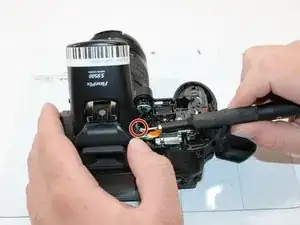
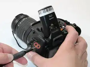
The second screw is on the right side of the camera, to the right of the strap mount.
-
-
-
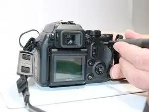
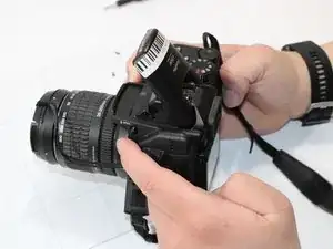
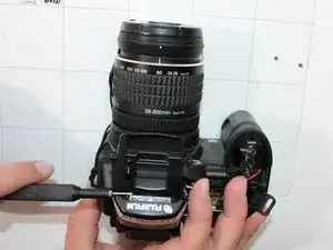
To open the case, gently push upward in the area just below the command dial with your thumb.
-
To release the catch located on the left of the command dial and at the base of the flash, place your thumb to the right of the command dial and push upwards at a 45° angle towards the flash.
-
-
-
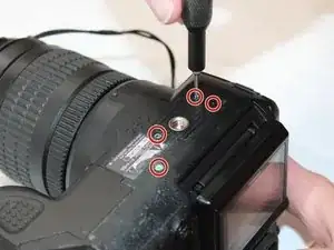
On the bottom of the camera, there are four M1.7 x 3.5 philips screws that will need to be removed.
-
-
-
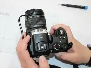
On the left side of the camera, there will be a USB adapter cover. There are two screws located directly above it.
-
There is also another screw located on the left side of the base of the flash that needs removed.
-
-
-
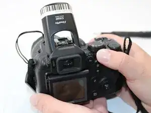
To remove the back case, look for the area on the left where you can place your thumb and pull it towards you. It should have 15 small notches divided into three rows of four and one row of three.
-
-
-
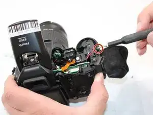
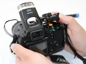
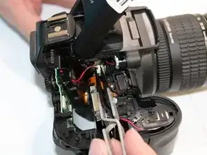
To the left of the AE-L dial, there is a brace that needs to be removed. Take out the screw from that panel.
-
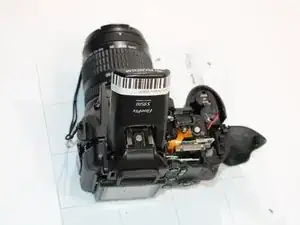
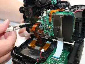
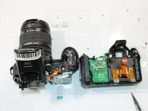
Remove the white LCD FPC from the camera back and the orange LCD FPC from the main body to separate the camera. Start by gently pulling the white LCD FPC away from the back of the camera, then remove the orange LCD FPC from the main body of the camera.
-


To reassemble your device, follow these instructions in reverse order.