Introduction
This guide presents a possible solution to the “Opening brakes fail” error on the Franka Emika Panda robot. A robot experiencing this issue will not unlock its brakes when commanded through the Franka Desk interface. It will unlock up to the broken joint then display the error message on Franka Desk. While attempting to unlock the broken joint, the robot may produce a weaker clicking noise compared to a functional joint.
In the following will use joint 5 (J5) as an example. By convention, joint 1 (J1) refers to the joint closest to the robot base, and joint 7 (J7) is the one closest to the end effector.
Tools
-
-
Remove the fairing preceding the broken joint, i.e. the last non-moving link fairing when the broken joint is actuated.
-
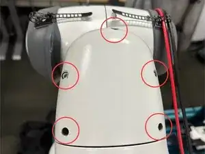
For J5, this requires removing the 5 screws on the front and 2 screws on the back.
-
The screws should be 2.5mm hex but may depend on the specific robot. The lengths may be different so do keep track of where each screw came from.
-
Use caution when unscrewing as they are easily stripped.
-
-
-
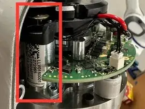
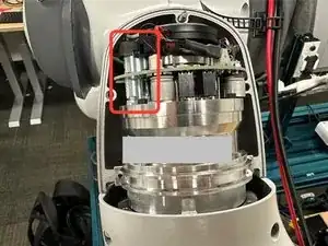
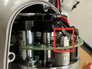
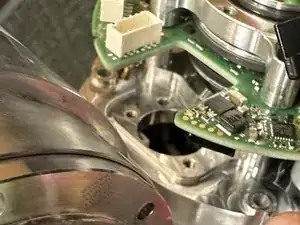
The location of the locking solenoid is illustrated with the red box.
-
Confirm that the solenoid is indeed broken by attempting to unlock the robot through Franka Desk UI.
-
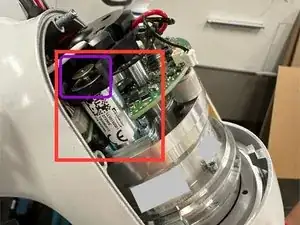
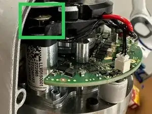
The bronze pin (purple box) should actuate upon unlocking and stay in the "up" position. In a broken solenoid, the pin will not stay up.
-
The green box shows the "up" position of a functional solenoid. Note that the bronze pin is no longer flush with the lower part of the black cap.
-
See step 7 of the guide for a video of the nominal unlock behavior.
-
-
-
Power off the robot and disconnect the cable to the Franka Control Box.
-
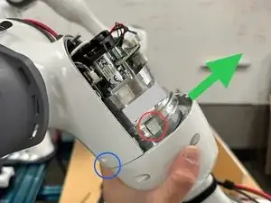
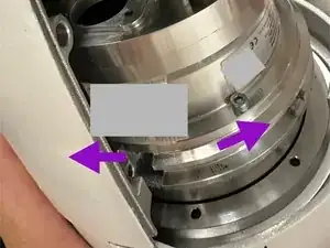
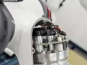
Gently move the robot arm in the direction of the green arrow while supporting the weight of the arm.
-
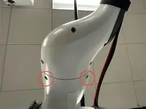
Notice the gap on the fairings (blue circle) once the arm has been moved.
-
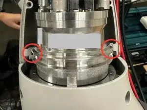
The screw boss blocks (red circle) are present on both sides of the robot. Tap on them lightly to remove.
-
After removing the screw boss blocks, the actuator assembly and everything downstream of the broken joint should be free to rotate along the purple arrows.
-
The actuator is still locked and does not contribute to the rotation.
-
-
-
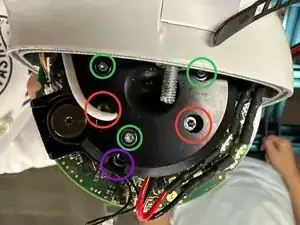
Remove the 3 screws circled in red, which holds the black cap onto the actuator assembly.
-
The design of the black cap may vary slightly depend on the robot joint. Here J5 is pictured.
-
The screws circled in purple do not need to be removed.
-
The screws circled in green do not need to be removed.
-
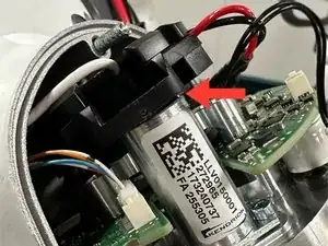
Once the screws are removed, the black cap can be lifted up slightly, as illustrated by the red arrow. There is no need to remove the black cap.
-
-
-
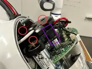
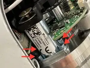
Disconnect the 2-pin connector (in red box) connecting the locking solenoid to the main PCB.
-
Remove the 4 M2 screws (red arrows) that fasten the locking solenoid.
-
The locations of the screws may be obstructed by the robot fairing, PCB, and the black cap.
-
Rotate the robot (see step 3) and shift the black cap around (see step 4) to gain access to the screws.
-
Be careful not to damage any cables or protruding electronics.
-
-
-
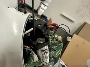
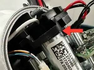
Lift the black cap slightly as illustrated by the red arrow.
-
The cap needs to be lifted so it doesn't block the locking solenoid on its way out.
-
Extract the broken locking solenoid.
-
Some light wiggling and prying with a spudger at the mounting interface could be helpful.
-
-
-
Insert the new locking solenoid and follow the steps in reverse to reassemble the robot.
-
The locking solenoid can be actuated once the two pin connector is plugged in. In case the replacement has not been confirmed to work.
-
Once the robot has been reassembled, connect the control box and perform unlock to verify the repair. You have now fixed your robot!
