Introduction

Use this guide to replace the mainboard, along with the heatsink, in your Framework 16" laptop.

Note: the laptop used in this guide is a generic setup of one US keyboard, one numpad module, and two touchpad spacers. Your setup might vary, but the procedure should remain the same.

  1. FyZqYQXlGGSUVdfO
    FyZqYQXlGGSUVdfO
    ddbQkHnXk5QEvLfj
    • Unplug all cables and fully shut down your laptop.

    • If your repair requires a spudger, a T5 Torx, or a Phillips screwdriver, you can use the included Framework screwdriver. Whichever works best for you!

    • Framework recommends that you put your laptop into battery disconnect mode in the BIOS whenever removing the battery. Read how to do that here.

    • To disable this mode, click here.

  2. HJK3VU1YKTOBcZWU
    HJK3VU1YKTOBcZWU
    IuUQcOxBhlr1wW2M
    OEbqAZAWwaDAxM3B
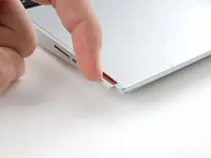
    • Flip your laptop over and find the two locking tabs beneath the expansion cards.

    • Pull the locking tabs down to unlock the rows of expansion cards above them.

    • The locking tab will show red when it's unlocked.

  3. mggvLJWLFTZwA6Jx
    mggvLJWLFTZwA6Jx
    SMTLCxHoi1CnSjQ4
    ZXfgdxhDu5iHQC2X
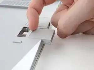
    • Insert your fingernail over the white rubber lip along the inner edge of the expansion card.

    • Pull the card away from the laptop to disconnect it.

    • This might take some initial force. If you're having trouble, make sure the locking tab is properly unlocked.

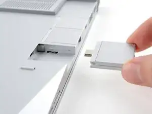
    • Slide the card completely off its rail and remove it.

    • Repeat for all of the expansion cards.

    • During reassembly, align the new card on the rail and push it in until it sits evenly with the edge of the laptop.

  4. V3IQJtBJkQSCnAu6
    V3IQJtBJkQSCnAu6
    abI2FGam4QCkWG3m
    DT1dF4lTE66QHXQJ
    • Use your fingernail to pull out the two Input Module latches and unlock them.

    • The latch will show red if it's unlocked.

  5. oRA2BGYySG6cv4UI
    oRA2BGYySG6cv4UI
    EjHQwVWhreadODGC
    Qd4HyChkTncRj6NB
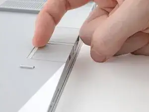
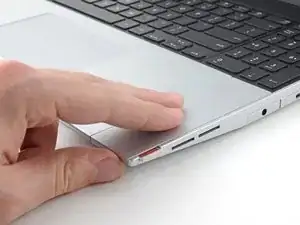
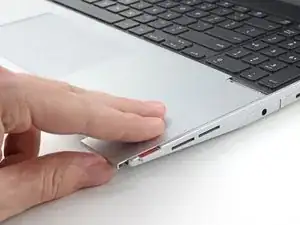
    • Use your fingers to slide the touchpad spacer toward the bottom edge of the laptop and unclip it.

    • If you're having trouble, check if the corresponding Input Module latch is properly unlocked.

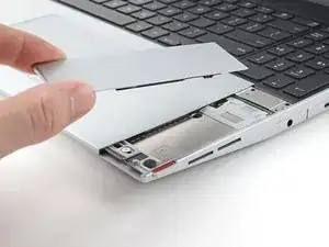
    • Lift the touchpad spacer off the laptop and remove it.

  6. PIQuXTPBOmiCmpTP
    • Repeat the same procedure for the other touchpad spacer.

  7. XUyEDC4iKWYV5Tnt
    XUyEDC4iKWYV5Tnt
    pTmsgnLnOsotLW2D
    IAOYbMHag2mlLGT6
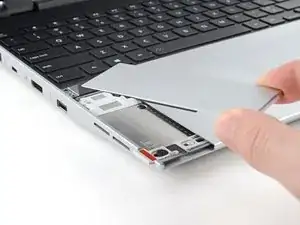
    • Use your fingers to slide the touchpad toward the bottom edge of the laptop and disconnect it.

    • If you're having trouble, check if the Input Module latches are properly unlocked.

    • Lift the touchpad and remove it.

    • During reassembly, perform the following:

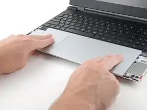
    • Place the touchpad flat on its cutout so its clips are properly aligned.

    • Press the touchpad down and slide it into place so it lines up evenly with the bottom edge of the laptop.

  8. EMiltNMDCZ2ZfrqP
    EMiltNMDCZ2ZfrqP
    kI1lOpjnUTZDpfZt
    5UtiQGpQXVRbA4QM
    • The keyboard is held in place with strong magnets. Apply gradually increasing force to avoid having the keyboard violently eject.

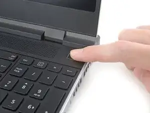
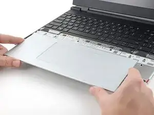
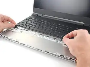
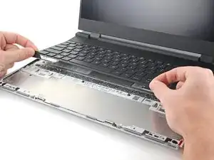
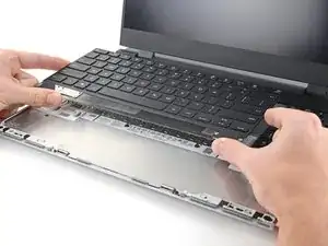
    • Grip the two pull tabs along the bottom of the keyboard.

    • Lift the pull tabs until the keyboard magnets release.

    • Remove the keyboard.

    • During reassembly, make sure the keyboard is seated properly on its alignment pegs and sits evenly with the edges of the laptop.

  9. F6EtPOhQyBDv3K5Q
    F6EtPOhQyBDv3K5Q
    fJDM6TD5UaZ5BvkI
    xeLqBn636iKVEMk2
    • The numpad is held in place with strong magnets. Apply gradually increasing force to avoid having the numpad violently eject.

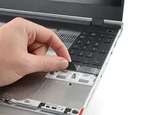
    • Grip the pull tab at the bottom of the numpad.

    • Lift the pull tab until the numpad magnets release.
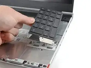
    • Remove the numpad.

    • During reassembly, make sure the numpad is seated properly on its alignment pegs and sits flush with the edges of the laptop.

  10. xSZxvNPTOAuYkaWT
    xSZxvNPTOAuYkaWT
    BXKvddQEfXVikjYU
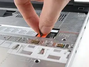
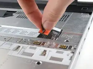
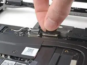
    • Grip the black pull tab on the midframe cable press connector.

    • Lift up to disconnect the midframe cable.

  11. pqZIeK5rgaKTBWl4
    pqZIeK5rgaKTBWl4
    4spVx1SupfNvWdAX
    • The midframe screws are ordered from 2–17 (number 1 is the press connector). You don't have to follow the order, but you can use it to help keep track of the screws you've loosened.

    • Use a T5 Torx screwdriver to loosen the 16 captive screws securing the midframe.

    • During reassembly, follow the order (starting with 2) to reinstall the screws across the midframe evenly.

  12. dEJBoYwWfHyy6nlt
    dEJBoYwWfHyy6nlt
    llEN3ecAxs5EgLIV
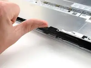
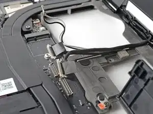
    • Use your fingernail to lift the bottom edge of the midframe enough to grip it with your fingers.

  13. Nb1ZVUXayRZOCKxm
    Nb1ZVUXayRZOCKxm
    hDGtDqQTgT6GsMW6
    • Lift the midframe off the laptop and remove it.

    • During reassembly, make sure the midframe sits evenly on its alignment pegs before tightening the screws.

  14. EGKuQxhWyjIjuZIq
    EGKuQxhWyjIjuZIq
    6QuZOpyj6LH5dvVQ
    • Use a T5 Torx screwdriver to loosen the three captive screws securing the battery.

  15. BPVogsAOsLdNbVN1
    BPVogsAOsLdNbVN1
    UaRXRJ4edO4MBBtc
    RSUowATAIjOPYONQ
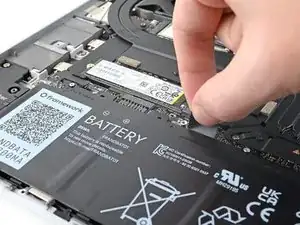
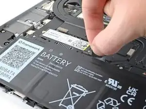
    • Grip the black pull tab at the top of the battery.

    • Lift the pull tab to disconnect the battery connector.
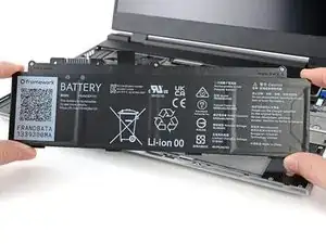
    • Remove the battery.

  16. R6AKOSxg2J2JAg3h
    R6AKOSxg2J2JAg3h
    26QhomyOahyIJeMR
    • Use a T5 Torx screwdriver to remove the 2 mm‑long screw securing the SSD.

    • The SSD might pop up at a shallow angle when you remove the screw.

  17. XOpo2nvkiSMhRZiC
    XOpo2nvkiSMhRZiC
    fNg6KnPTGR11EJ2L
    aTkPJ2VQ1kNAtGOx
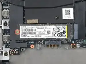
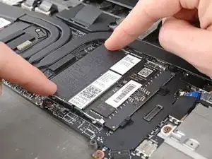
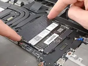
    • Grip the end of the SSD with the screw hole and slide it out of its socket.
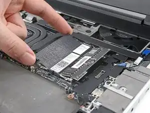
    • Remove the SSD.

    • If you're installing a secondary M.2 2230 SSD, remove the 2 mm‑long screw next to the gray thermal pad and follow the same removal procedure.

    • During reassembly, insert the SSD at a shallow angle into its socket, and hold it flat to the laptop while you reinsert its screw.

  18. fsBDCO3PlFRT2fCi
    fsBDCO3PlFRT2fCi
    m6CVJSfJrJ3idqJQ
    IFxahEqevYJNEsYK
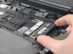
    • Push the two metal arms on each side of the RAM stick outward until they disengage and the stick pops up at a shallow angle.

    • Repeat for the other RAM stick.

  19. aE4HZjbvlEqNjxSb
    aE4HZjbvlEqNjxSb
    OCivxlDjQ6l6rawX
    w3VxVoo5SlxW3C2f
    • Slide the RAM stick out of its socket and remove it.

    • Repeat for the other RAM stick.

    • During reassembly, insert the RAM sticks into their sockets at a slight downward angle, then push down firmly until both metal arms lock the sticks in place.

  20. pXGb3GHNlpHIBHZg
    pXGb3GHNlpHIBHZg
    4bUsZnKetY22dd6U
    • Use a T5 Torx screwdriver to loosen the captive screw securing Wi-Fi card.

    • The Wi-Fi card might pop up at a shallow angle when you loosen the screw.

  21. SnrMuQKUIQFcBwkh
    SnrMuQKUIQFcBwkh
    3b5AwgrsyMZDKN1S
    • Slide the clear Wi-Fi card cover straight off the card and remove it.

  22. Vy2kiHBo5iOFTaxK
    Vy2kiHBo5iOFTaxK
    nIgEoW41SRpVIY1H
    • Grip the end of the Wi-Fi card with the screw hole and slide it out of its socket.

    • Don't pull the Wi-Fi card too far from its socket, as it's still connected by two cables.

  23. OY4R3mYMdwqqDVZn
    OY4R3mYMdwqqDVZn
    IaBygTrySMjZA1RU
    Nd2FpKjiUUs1a6Qk
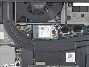
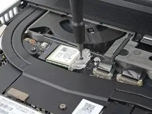
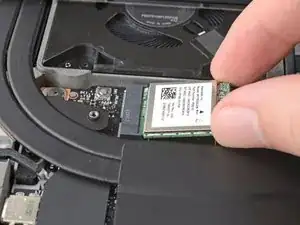
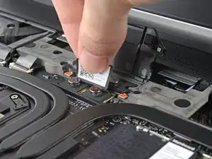
    • Insert the flat end of a spudger under one of the coaxial connectors, where the cable meets the metal head.

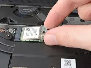
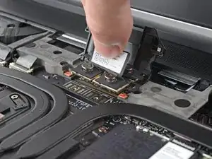
    • Lift the spudger straight up to disconnect the coaxial cable.

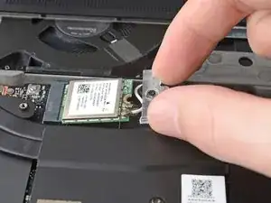
    • Repeat for the other coaxial cable and remove the Wi-Fi card.

    • During reassembly, refer to the arrows on the Wi-Fi card for which cable (black or white) a connector belongs to.

  24. YPDWdpOxdFAqThNw
    YPDWdpOxdFAqThNw
    4WGwAwjGwkx5HfPL
    • Lift the interposer door by its black pull tab and let it rest upright.

  25. Ek4knju1pQLgpVsV
    Ek4knju1pQLgpVsV
    4ThcI12HkB6MJMDI
    GwTbdOZvENb2BsWv
    • If you have the graphics module installed, your interposer will have four screws. Otherwise, you'll have three screws.

    • Lift the pull tab on the interposer and let it rest vertically to access all of its screws.

    • Use a T5 Torx screwdriver to loosen the three captive screws securing the interposer.

    • If you have the graphics module, use a T5 Torx screwdriver to loosen the four captive screws securing the interposer.

  26. tBOJVN4nDKMufmyS
    tBOJVN4nDKMufmyS
    iiPIb2EtkMDxoMaI
    • Lift the interposer by its pull tab and remove it.

  27. vDRVlx6RISCSiUcm
    vDRVlx6RISCSiUcm
    rNIm2MkOeEsmMxQQ
    • Use a T5 Torx screwdriver to loosen the two captive screws securing the expansion bay.

    • Close the interposer door before continuing.

  28. eRdCCLqmjDXwUxSv
    eRdCCLqmjDXwUxSv
    YkLYsxDNovXXOVGn
    RprGeTOOcKsUkmZH
    • Close your laptop and flip it over.

    • Slide the expansion bay out of the laptop and remove it.

    • The bay should slide out easily. If you feel any resistance, check if the screws holding it in place are fully loosened.

  29. MwFYQMSjITTeNKSV
    MwFYQMSjITTeNKSV
    PekFtZWDGadyhwo6
    tMQYf51be3nPpeee
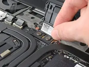
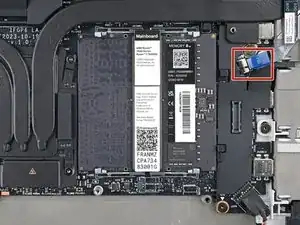
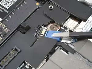
    • Use the flat end of a spudger, or a clean fingernail, to lift up the locking tab on the fingerprint sensor ZIF connector.

  30. RMKScpA6rP1ZkQns
    RMKScpA6rP1ZkQns
    OAXMJKmHwtJobHWQ
    • Use tweezers, or your fingers, to grip the blue pull tab and slide the fingerprint sensor cable straight out of its socket.

  31. P4D1jpQTWdmgusN2
    P4D1jpQTWdmgusN2
    FCCDpTENPKwmHqsP
    HfplRlsZXwfHGLwt
    • The fingerprint sensor cable is lightly adhered to the laptop frame.

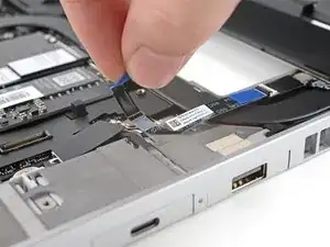
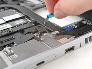
    • Use your fingers to peel the fingerprint sensor cable away from the frame and separate the adhesive.

    • During reassembly, if your adhesive is still sticky, press the cable to the frame to re-adhere it. Otherwise, use double-sided tape to replace the adhesive.

  32. YOdPakvsMSx1kUEI
    YOdPakvsMSx1kUEI
    gtJ5HGs5boUhC21u
    ZbZffqtrpmOvxE2U
    • The ventilation plate is held in place with magnets.

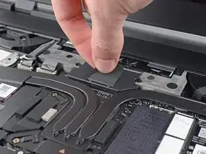
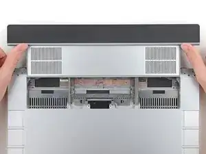
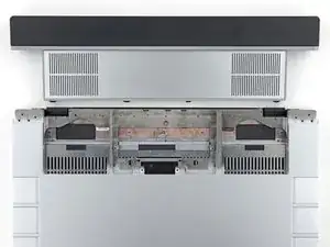
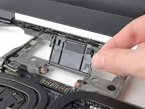
    • Lift the bottom of the ventilation plate and pull it away from the laptop until the magnets release.

    • Remove the ventilation plate.

  33. ykM5Rl6uRdkaHmDa
    ykM5Rl6uRdkaHmDa
    MTQweCcLYvSxbCho
    • Lift the speaker cable connector by its black pull tab and disconnect it.

  34. HQ5yJhpukP4UBABU
    HQ5yJhpukP4UBABU
    KHEkxmWk4GLV6cYD
    IJ6dDrneaaCTXMcG
    • Lift the two display connectors by their black pull tabs to disconnect them.

  35. 1bZQvENHqO33Fm2Q
    1bZQvENHqO33Fm2Q
    kYwXmRM3AQoMHCaK
    OkaTeaYugBXMJJLS
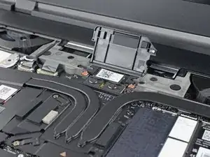
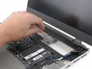
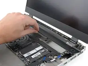
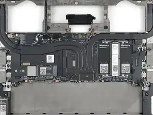
    • Lift the display and Wi-Fi card cables out of their slot in the frame enough to give room for the mainboard to lift straight up.

    • During reassembly, make sure the cables are routed properly in their slot so the midframe can sit flat on the frame.

  36. MFIw1vlDdGLT1rJ3
    MFIw1vlDdGLT1rJ3
    XcAiIXEFjrhusWxC
    b3PKUYmUxgiQQAVM
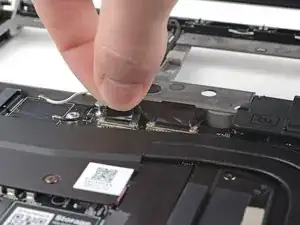
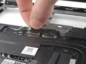
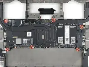
    • Lift up the interposer door to reveal the screw underneath.

    • The mainboard screws are ordered from 1–6. You don't have to follow the order, but you can use it to help keep track of the screws you've removed.

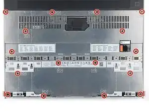
    • Use a T5 Torx screwdriver to remove the six 2 mm‑long screws securing the mainboard.

  37. wmWWdVAhDmsZolgN
    wmWWdVAhDmsZolgN
    OCSPEdypUCrIpLhT
    aNdGhfmJcJKlcurU
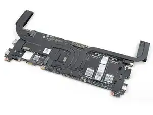
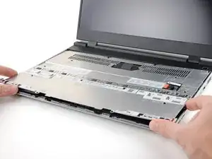
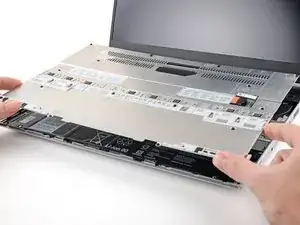
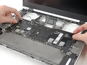
    • Grab the mainboard by the curving pipes of its heatsink.

    • Lift the mainboard off its alignment pegs and remove it.

    • During reassembly, make sure all of the cables are above the mainboard before securing it back to the frame.

Conclusion

To reassemble your device, follow these instructions in reverse order.

Take your e-waste to an R2 or e-Stewards certified recycler.

Repair didn’t go as planned? Try some basic troubleshooting, or ask our Answers Community for help.

Alex Diaz-Kokaisl

Member since: 16/01/22

151892 Reputation

0 comments