Introduction
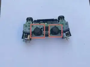
When using a joystick, it moves two brackets inside the analog stick in rotation and each of these brackets are attached to a potentiometer. The main function of a potentiometer is to measure the rotation and precise movement of the joystick. One potentiometer senses left and right movement while the other senses up and down movement. Inside the potentiometer there is a metal wiper that is attached to a white mounting bracket. When the bracket moves the wipers where it contacts the track changes which registers the joystick's position and movement. When malfunction of a joystick occurs, it is mostly due to the wear of the potentiometer. Over time, the wiper scrubbing back and forth against the resistance pad creates imperfection.
This guide will show you how to replace a damaged potentiometer from a DualShock 4 Controller (PS4 controller). The format for this guide can also be applied to a DualSense Controller (PS5 controller).
You do not need any special skills to perform this guide.
As for where to buy the potentiometer replacement, I recommend buying it from Amazon. The link I provided for the potentiometer replacement in the tools section is costly, you can find more cheap options from the Amazon website.
-
-
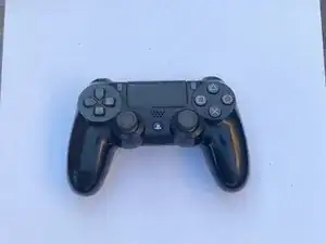
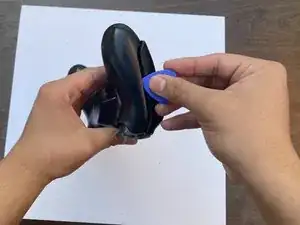
Grab you're DualShock 4 Controller that has joystick problems.
-
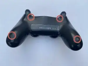
Using the Phillips #00 Screwdriver, remove the four 6.0 mm screws securing the rear cover to the controller.
-
-
-
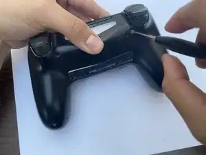
Pinch the handle of the controller to introduce an opening.
-
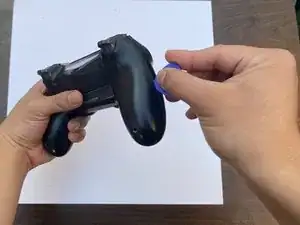
Wedge the opening pick tool into the opening then slide it to any direction.
-
Open the casing.
-
-
-
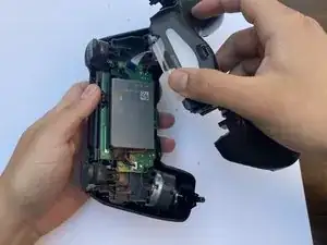
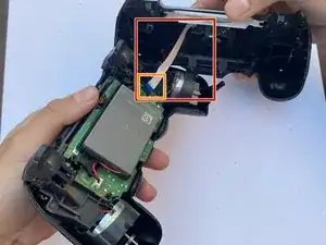
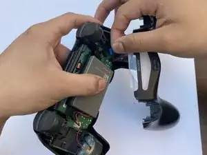
After carefully opening the casing, notice the white strip connected to the motherboard.
-
Grab the white strip by the blue end and carefully remove it.
-
-
-
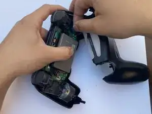
After removing the first half of the casing, you will be able to see the battery.
-
Disconnect the battery from the motherboard via the white connector.
-
Remove the battery.
-
-
-
Remove the battery case by simply pulling it out.
-
In other models, the screwdriver will be holding down the battery case.
-
-
-
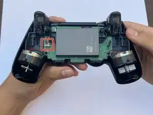
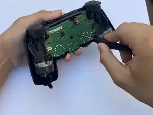
Using the same Phillips #00 Screwdriver, remove the 6.0 mm screw securing the motherboard and the other half of the controller case.
-
-
-
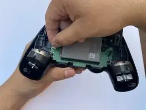
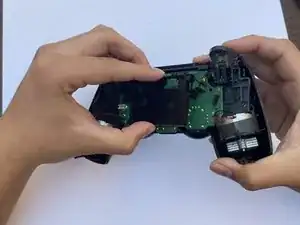
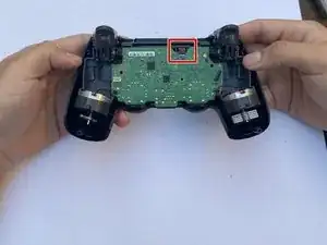
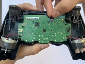
Notice the strip connected to the top of the motherboard. Disconnect it using your own fingers.
-
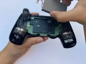
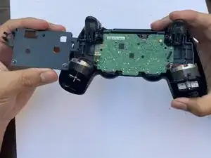
Separate the other half of the controller casing from the motherboard.
-
-
-
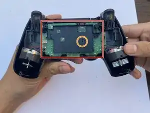
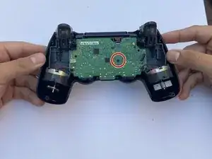
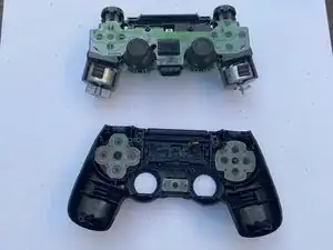
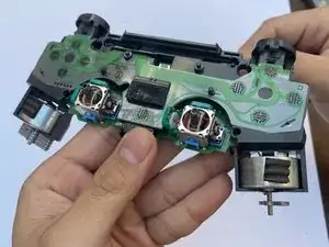
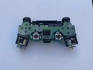
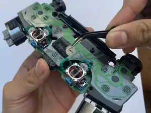
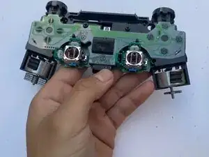
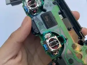
You will be focusing on the part with the motherboard.
-
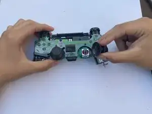
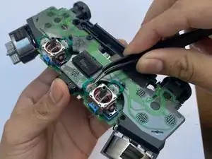
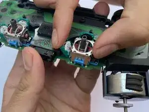
Remove the thumbstick from the joystick that is malfunctioning. If both joysticks are malfunctioning then remove both thumbsticks.
-
-
-
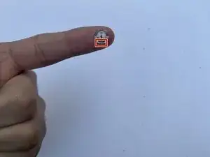
Grab your Potentiometer Replacement
-
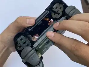
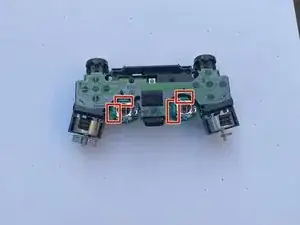
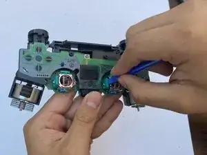
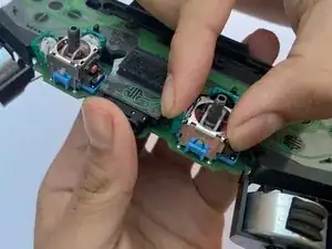
Using Tweezers, place the potentiometer replacement into the case.
-
Place the potentiometer replacement in a position where the two dots at the bottom of it is placed at bottom of the case.
-
-
-
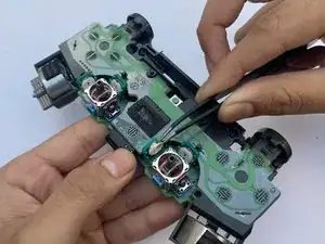
Make sure the hole of the potentiometer replacement aligns with the follower (in this first image, it is the orange plastic sticking out).
-
After everything is secure, close the case containing the potentiometer replacement.
-
To reassemble your device, follow these instructions in reverse order.
2 comments
How the replacement of the metal springs should it repair the issue? isn't the conductive graphite in the green part of the potentiometer the part worned out?
i would say it's both, before replacing the stick (or for inexperienced the whole pad) you could try cleaning the conductive graphite with a qtip with isopropyl alcohol, and that little curved metal part on the metal spring.
To me it didn't work but I haven't done it properly yet, I'm planning to retry it
chief -
Make sure when preparing to do this repair you check what replacements you need. There is 2 different styles that Sony has used.
Sam Closser -