Introduction

Here is a DualShock 4 controller that had a drift to both analog joysticks. Fairly straight forward replacement of the joysticks resolved the issue.

The joysticks are soldered to the controller board. You'll need a soldering station to complete this repair.

  1. X5wSfxicAxSko1Zg
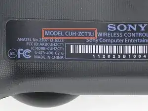
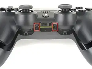
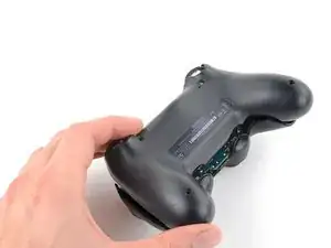
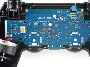
    • Check the model number on the back of your controller. This guide was written using model CUH-ZCT1U. If you have another model, the guide procedure and replacement parts may differ slightly.

    • If you have the second generation DualShock 4, model CUH-ZCT2U, use these guides.

    model:cuh-zct2e

    كيف يمكن ان افكها

    Mhmod -

  2. w1u5HLFRbQIP2d2F
    w1u5HLFRbQIP2d2F
    pJuWDOWVmAmLyI6V
    • If you need to stabilize your controller during this repair, lay it on a soft surface such as a microfiber cloth.

    • Use a Phillips screwdriver to remove the four 6.4 mm-long screws securing the rear case.

    to re-torque these PH00 screw... i found 19Ncm to be about the max. (since 27Ncm was too much)

    Dreamcat 4 -

  3. NgnhjUOrfuwMJyov
    NgnhjUOrfuwMJyov
    cwbJVa63FyosD31P
    HvrmieUp6UwVcySs
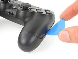
    • Use an opening pick to pry each corner of the L1 button from the front case.
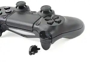
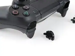
    • Cover the button to prevent it from ejecting out of your workspace.

    • Remove the button.

  4. AJugiOXGbAhQ1BMq
    • Use your opening pick to pry and remove the R1 button, just as you did for the L1 button.

  5. B1xF1WqHbfBoBJtF
    B1xF1WqHbfBoBJtF
    EHOhhIPKfA2DZQfI
    McHyyAQtKhIUOHJO
    • Six plastic clips secure the rear case to the front case. The next four steps demonstrate how to release these clips before you can open the controller.

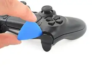
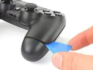
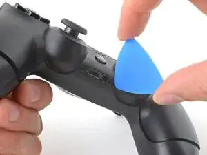
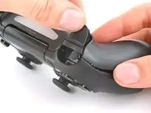
    • Insert your opening pick at a downward angle between the front case and rear case, halfway between the handle and the action buttons.

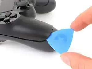
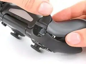
    • Slide your pick toward the handle and pry up to release the first clip.

    • Repeat this procedure on the other side of the controller to release the second clip.

  6. j1WZgSo6o3TaODlg
    j1WZgSo6o3TaODlg
    eRF1MNwAMFijHfw4
    ocNfVkqvnbtCNBcd
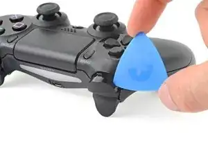
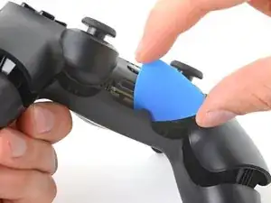
    • Two more clips secure the rear case near the extension port and the headphone jack.

    • Insert your opening pick between the front case and rear case at either side of the ports.

    • Twist your pick to unclip this section of the rear case from the front case.

    • If the rear case feels stuck, insert and twist your pick from different angles.

    • Don't open the controller yet, as it's still held together by two very delicate clips near the triggers.

  7. jf5SveEdOwRIGhJq
    • The final two clips are very delicate, and must be disengaged from inside the controller. If you break them, don't worry—it won't affect this repair or your controllers functionality.

    • Locate the clips by looking through the gap above the R2 or L2 buttons.

  8. qQcyUfycauX1EUE6
    qQcyUfycauX1EUE6
    YFUPEeSZZqPY4U1E
    OHcMVCNj4VJZWyNC
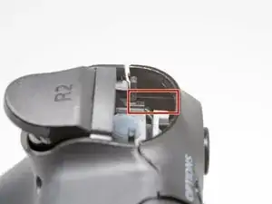
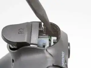
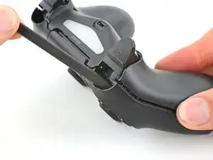
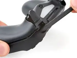
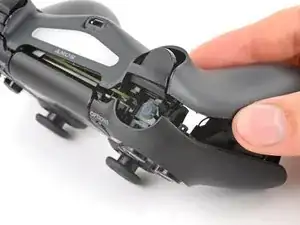
    • Insert the point of a spudger through the gap above the R2 button and push the retaining clip outward.

    • While pushing the clip outward, slowly pull the rear case away from the front case until you feel them separate.

    • Don't fully open the controller until each of the R2 and L2 clips have been disengaged.

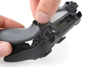
    • Repeat this procedure for the clip near the L2 button.

  9. PKcRjl2CIQogpTKp
    PKcRjl2CIQogpTKp
    fip3U51QOcVGEXVJ
    u6ZnJrwXE1clORUW
    • Press the R2 button and slide the rear case over it.

  10. KP2vxXGWlaTfsUDK
    • Press the L2 button and slide the rear case over it.

  11. 3hhTNdLYVWIBGeVA
    3hhTNdLYVWIBGeVA
    hfTvkNdF3uokn4Pa
    GXsRCZqUChYpLy1d
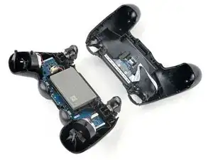
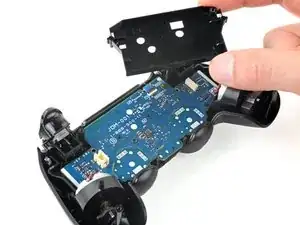
    • Flip the rear case over the top of the controller and lay it down, being careful not to strain the interconnect cable.

  12. nCng6Fw1GK6utOG1
    nCng6Fw1GK6utOG1
    SZUVqTnFbaQPaXbq
    5sWqh1SoSQhBsOFd
    • Use tweezers or your fingers to remove the interconnect cable by pulling its blue pull tab straight out of the socket.

    • During reassembly, reconnect the cable with its blue pull tab facing the outside of the controller.

    On the model CUH-ZCT2E the circuit board is mirrored so that the connection is on the left side. When reassembling the blue tab should be facing inwards.

    Konrad Skeri Ekblad -

  13. bTlYAQTvGVBKbfRV
    bTlYAQTvGVBKbfRV
    4QAyFxp5cWR2HTHW
    • Use tweezers or your fingers to grab and disconnect the head of the battery cable from the motherboard.

    • Only pull on the head of the connector—don't pull on the cable itself.

  14. gp4YHL5LMwLLvcoE
    • Remove the battery.

  15. 6M2oWXxExT4ElTXk
    6M2oWXxExT4ElTXk
    FwVprSgDuD6bHjCd
    • Grab and remove the reset button extension from its recess in the battery bracket.

    On the model CUH-ZCT2E this is part of the battery bracket and not removable. Just skip this step.

    Konrad Skeri Ekblad -

  16. OdOvSwnMxMWM4r1W
    OdOvSwnMxMWM4r1W
    mGrvIhfZTUenHG4w
    R1xtscUk6ivQwlFS
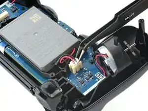
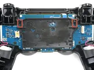
    • Locate the two clips securing the battery bracket to the motherboard.

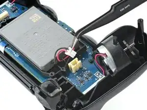
    • Insert the point of your spudger into the opening behind the right bracket clip.

    • Depress the clip to disengage it from the motherboard.

    • Lift up the right edge of the battery bracket.

    On the model CUH-ZCT2E the battery bracket is not secured by clips but by a PH #00 screw mid height on the right half of the battery bracket. Just remove the screw and for the next step lift the battery bracket straight up.

    Konrad Skeri Ekblad -

  17. MpRnnXNR6AkVJPdE
    MpRnnXNR6AkVJPdE
    JknRtEahfZLV1Rus
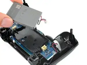
    • Insert the point of your spudger in the opening behind the left bracket clip.

    • Depress the clip to disengage it from the motherboard.

    • Remove the battery bracket.

  18. NtpB2BKLXfOs3ibt
    NtpB2BKLXfOs3ibt
    ocmExNqCRtHeRbfY
    L2nX3BGEGvqBGKhL
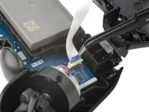
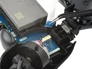
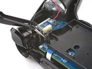
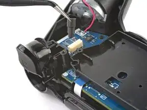
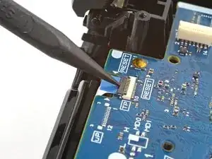
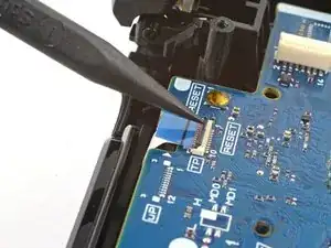
    • Use the point of your spudger to flip up the locking flap securing the touch pad cable ZIF connector.

    • Use tweezers or your fingers to disconnect the cable using its blue pull tab.

  19. 1aIuIlkWcAAVXAKD
    • Use your Phillips screwdriver to remove the 6.4 mm screw securing the motherboard.

  20. ouIZjDmNVCOuSSKT
    ouIZjDmNVCOuSSKT
    bx3YdyxTxUCJetoE
    VohkAs4xxPTNHEhL
    • Be careful not to strain the vibration motor cables. Follow this guide to re-solder the vibration motors if they break off the motherboard.

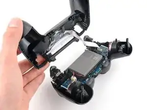
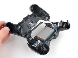
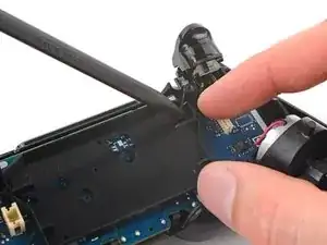
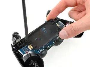
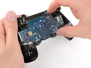
    • Lift the motherboard from the midframe.

    • Guide the analog stick covers through their cutouts in the front case.

    • Flip the motherboard over the bottom of the controller, leaving the vibration motor cables attached.

  21. RJZsy2UqiRSEnPn5
    RJZsy2UqiRSEnPn5
    wIwhvIGJvTe1k3Qp
    JBWmJbM5vCTkbVmJ
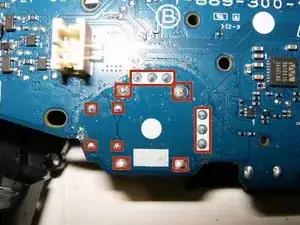
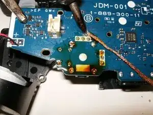
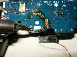
    • These are the solder connections that will need to be desoldered. Since the board is upside down, left will become right.

    • Use a desoldering wick and flux to melt and remove the solder

    • This may take a bit of practice since all the solder will have to be removed. It does help to pull a bit on the joystick while melting the solder and using the wick.

    I'm new to solder/desoldering but i've been unable to get the solder to really melt or come loose enough to remove during this step. i have a solder remover/sucker but alas no luck.

    any recommendations?

    James Napoli -

    You need heat, solder wick (skip the solder sucker, those never work for me;-) and lots of flux. Place flux on your wick and tin the tip of your soldering iron with solder as well.

    oldturkey03 -

  22. j6B2TtUrGadEMZgd
    j6B2TtUrGadEMZgd
    4bU3mNAmOZLOiQKu
    ni61vqWx5Tix6MH4
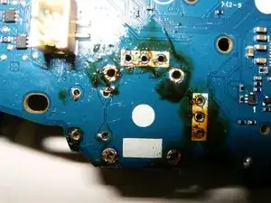
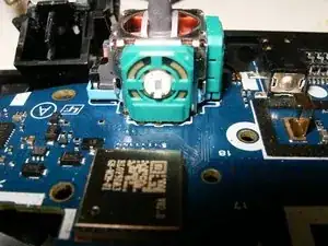
    • Once all the contacts are desoldered, the old joystick can be removed.

    • Check that all the holes are cleared of old solder. Hypodermic needles as well as very small drill bits can be used to clear the holes.

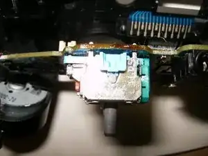
    • Insert the new joystick into the circuit board. Make sure it is properly seated and that all the contacts line up with the holes in the circuit board.

  23. THZCp2cwEdNjRTHZ
    THZCp2cwEdNjRTHZ
    l3PLMUUkYBrkSOnF
    oHFPZvIyqCUYOngV
    • Double check to make sure the joystick is seated properly.

    • Solder all the contacts to the board.

    • Here is the board after the repair. All that is left is to clean off the old flux with some isopropyl alcohol.

Conclusion

To reassemble your device, follow these instructions in reverse order.

oldturkey03

Member since: 29/09/10

805760 Reputation

14 comments

I just tried to remove both joystick and replaced them but unfortunately only one joystick works and that one that works it's stuck on and only moves in one direction.

Juan Hernandez -

I've not been able to actually get the solder out, would love any suggestions or tips.

James Napoli -

send me a couple of pictures on what your repair looks like thus far. Send them to my email. Click on my username and my email address is on my profile. Let's see what you got so far.

oldturkey03 -

This is a very difficult repair, what this guy didn't mention is you need a very expensive solder station with an electric solder sucker. The solder needs removing and it's nearly impossible without damaging the tracking.

Dave bolton -

You definitely need some soldering experience but the repairability is not that difficult. The soldering points are big enough for any cheap ($40) soldering iron can get too. As for removing them, it helps to use flux and also a soldering wick to absorb all the old solder. It is not easy but not the most difficult repair. P.S you do not need the expensive soldering stating with hot air etcetera. This works perfectly as it get hot beyond the required point to melt the solder

Eyob Grainge -

I've been repairing ps4 controllers along time and this isn't an easy fix. You need an electric solder sucker, to get all the solder out the holes with danagimv the tracking is near on impossible with a good solder

Dave bolton -

@dave2003 “what this guy didn't mention is you need a very expensive solder station with an electric solder sucker “, nope! All I used what a run-of-the-mill soldering iron and some soldering wick and flux. This is a straight forward repair that does not require any special tools!

oldturkey03 -

Can someone suggest a good soldering gun and soldering metal ?

mine is for very thin wires.

Animeiat A -

What is the best soldering gun yet affordable that I can use to solder this in place ?

mine only works for thin wires.

Animeiat A -

Pro tip: If the button works properly and you only need to fix 1 axis, you only need to remove the 3 pins that holds the potentiometer. You can snap off the potmeter from the metal casing of the stick and replace that part only if you have a compatible one but you need to be carefull, as there are multiple size of analog sticks with different potmeters on the sides and sometimes the shaft doesn’t match. But if you have multiple spares analog stick you can try to find a matching one.

Dukefazon -

I took the ps4 controller apart, and the video I was watching said to pop off the green things that are around the analog stick with white things inside them, they have tiny pieces on top and bottom, i’m missing that little peice, does that matter

tonya turner -

ジョイスティックを外した状態で

入力されている場合治りますか?

gogulu -

Link to purchase part takes you to N64 joystick part. Doesn't appear to be correct?

Stephen Hotchkiss -

thank you🙏🏽

Ossama عادل -