Introduction

  1. AeyHbr6H4nTMxf6O
    AeyHbr6H4nTMxf6O
    DhnZHIrmxAVHryCX
    • Remove the two 8 mm Phillips #0 screws on the back cover.

    • The motherboard connects the two covers together. DO NOT separate the two yet.

    • There is a button that loosens as the Phillips screws are removed. Don't be alarmed if it falls out.

  2. bRSDmuJFSaSPpcbC
    bRSDmuJFSaSPpcbC
    CyuYqB4l6O2RlZXR
    • Remove the four 6mm Phillips #0 screws connecting the motherboard and front cover.

    • DO NOT detach the wire connecting the motherboard to the front cover.

  3. 1OmJyPFUpl2vOMjT
    1OmJyPFUpl2vOMjT
    g5iF2efpoYXl2Hvr
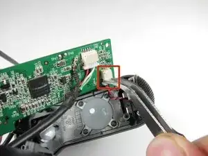
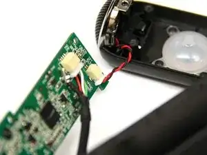
    • Grasp the white wire connector between the tabs and the socket.

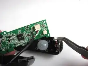
    • Wiggle the connector back and forth to remove the front cover from the motherboard.

Conclusion

To reassemble your device, follow these instructions in reverse order.

Timothy Forrest

Member since: 18/04/13

19 Reputation

One comment

This guide doesn’t show a motherboard and is a copy of this other guide (for a webcam):

Logitech Webcam Pro 9000 Microphone Replacement

Maximilian Cohan -