Introduction

This repair guide was authored by the iFixit staff and hasn’t been endorsed by Google. Learn more about our repair guides here.

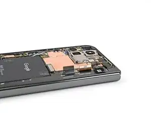
Use this guide to replace the USB-C port board in your Google Pixel 9 Pro Fold.

  1. oJjMp1p2qPpIDZAJ
    • Let your phone's battery drain below 25% before starting this repair. A charged lithium‑ion battery may catch fire if damaged.

    • Unplug all cables from your phone and completely power it down.

  2. eTmJydwESkDseema
    eTmJydwESkDseema
    aa3qhEvEDj6yHm11
    jbuhiFDgPymVlJQD
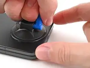
    • Apply a suction cup to the back cover, as close to the center of the bottom edge as possible.

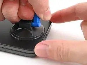
    • While securing the phone with one hand, pull up on the suction cup with strong, steady force to create a gap between the back cover and the frame.

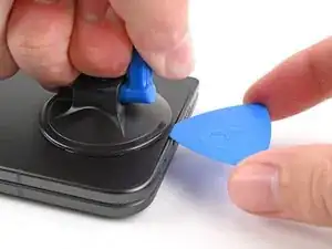
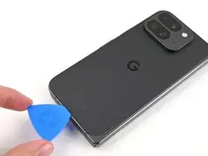
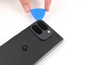
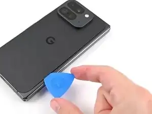
    • Insert an opening pick into the gap.

    • If your back cover is badly cracked, covering it with a layer of clear packing tape may allow the suction cup to adhere. Alternatively, very strong tape may be used instead of the suction cup. If all else fails, you can superglue the suction cup to the broken back cover.

  3. UZvmWmyDaMSKEAPs
    UZvmWmyDaMSKEAPs
    UbqfRkNWj1XfoXq1
    lMZVC6coFycrGEQo
    • During the next two steps, don't insert your opening pick deeper than 3 mm to prevent damaging the metal springs around the frame.

    • Optionally, you can measure and mark your opening pick at 3 mm to help you visualize the length.

    • Remove the suction handle from the back cover.

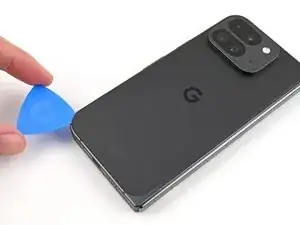
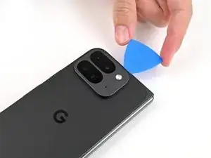
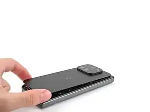
    • Slide the opening pick around the bottom left corner and up the left edge of the back cover to separate the adhesive.

  4. pjhoqRTyTviaemYo
    pjhoqRTyTviaemYo
    odTUHQI1bdQI1MJA
    ZgVbpDBEdSL42IGC
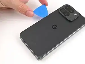
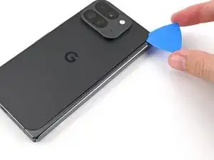
    • Continue sliding the pick around the top left corner and across the top edge of the back cover.

  5. CaasdZGU4FgOkwDI
    CaasdZGU4FgOkwDI
    rEDGbYqJxGLCJmFt
    qVZJ1RLLExOZsYga
    • The adhesive along the right edge of the back cover is thicker than the rest. You'll need to insert your opening pick at a minimum of 4 mm to separate the adhesive.

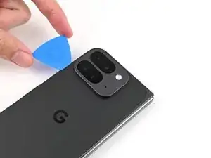
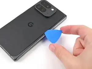
    • Slide your pick down the right edge and around the bottom right corner to separate the remaining adhesive.

  6. uBbicSFEuASALPUY
    uBbicSFEuASALPUY
    s1RRIqs6LTZnBgOU
    SgTxtNmkdWrCI1iQ
    • Don't fully remove the back cover yet, as it's still connected to the phone by a cable.

    • At this point, the back cover should be free from the frame. If there's still resistance around the edges, use an opening pick to separate any remaining adhesive.

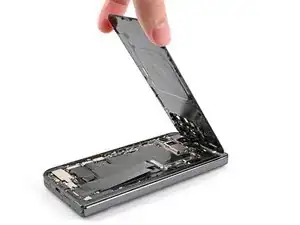
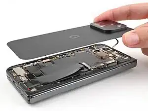
    • Lift the bottom edge of the back cover and swing it over the top edge of the phone.

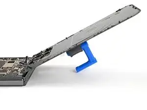
    • Prop up the back cover with your suction handle or a clean, sturdy object—making sure that the cable isn't strained.

  7. hRIxCC1MpvjnQMya
    hRIxCC1MpvjnQMya
    2bspQCbDC5Uenknh
    • Throughout this repair, keep track of each screw and make sure it goes back exactly where it came from.

    • While the Pixel 9 Pro Fold uses Torx Plus screws, standard Torx bits also work. Use the same size or one size larger (T3 or T4 Torx bits with 3IP Torx Plus screws) and apply constant, downward force to prevent stripping.

    • Use a Torx Plus 3IP driver to remove the 3.0 mm‑long screw securing the top bracket.

  8. 6KwDVuRmbIsSZ1Bk
    6KwDVuRmbIsSZ1Bk
    1YVsLTrikIxiRuc4
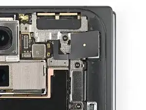
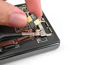
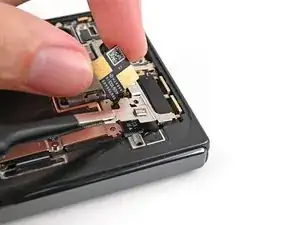
    • Use tweezers, or your fingers, to pull the top bracket towards the top of the phone to release it from its clip.

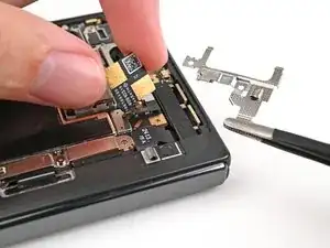
    • Remove the top bracket.

  9. IOpYw6eNxhEimWHF
    IOpYw6eNxhEimWHF
    OLcMQnPbx2RECKET
    • Insert the tip of your spudger under the bottom edge of the back cover cable press connector.

    • Don't insert your spudger anywhere else, as you risk dislodging surface‑mounted components.

    • Pry up and disconnect the back cover cable.

  10. iU6uFI1WbWBtRbLb
    • Lift the back cover off the frame and remove it.

  11. c3UDskiawmgL5G3I
    c3UDskiawmgL5G3I
    gMSM1sPyMfIDF4YQ
    • Use a Torx Plus 3IP driver to remove the two 3.0 mm‑long screws securing the base battery bracket.

  12. j34hdeHwldj5FF4y
    j34hdeHwldj5FF4y
    A1nO1lZiTSHCvIdF
    T4ofKxcrlWCChvvE
    • Use tweezers, or your fingers, to pull the base battery bracket toward the bottom of the phone to release it from its clip.

    • Remove the base battery bracket.

  13. tVFRWNIFULsbeLUl
    tVFRWNIFULsbeLUl
    wBcNuHnugXQbxMwK
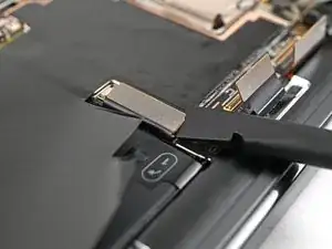
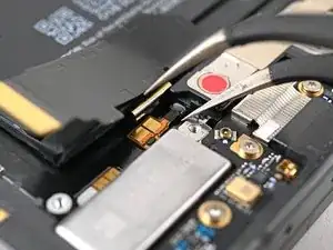
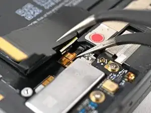
    • Insert the tip of your spudger under the bottom left corner of the base battery press connector, near the gold marker.

    • Don't insert your spudger anywhere else, as you risk dislodging surface‑mounted components.

    • Pry up and disconnect the base battery.

  14. jjbCYqq6YmOsOvSY
    jjbCYqq6YmOsOvSY
    cjmLGQJw2UVipPyL
    • Use a spudger to pry up and disconnect the USB-C port board cable press connector.

  15. KxYfjErbITHhTCqR
    KxYfjErbITHhTCqR
    eWhmmcoKap2ZPcL2
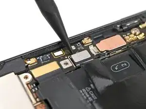
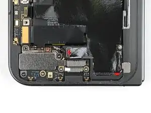
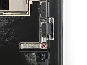
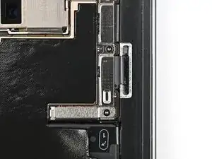
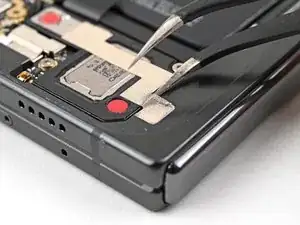
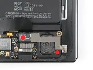
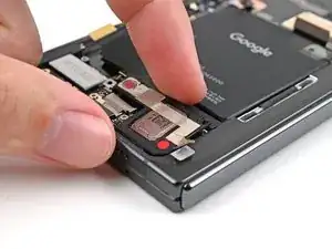
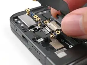
    • Use a Torx Plus 3IP driver to remove the two 3.0 mm‑long screws securing the vibrator bracket.

  16. BbHKTUt6qBucDaDR
    BbHKTUt6qBucDaDR
    CwOCCFUVdOOthWxv
    • Use tweezers, or your fingers, to lift the vibrator bracket off the frame and remove it.

  17. OvkftMhCqAlrxOnX
    OvkftMhCqAlrxOnX
    WC5tGMSIqGksARNX
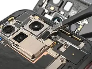
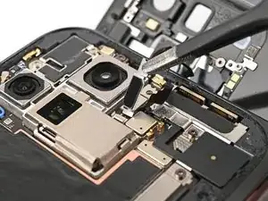
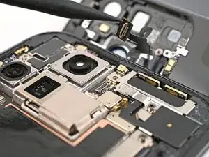
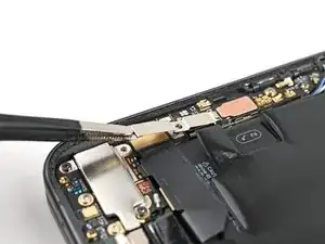
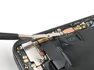
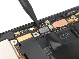
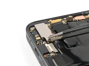
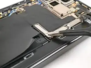
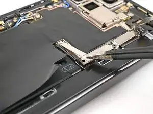
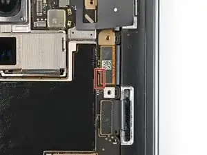
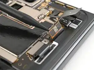
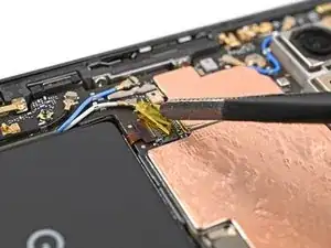
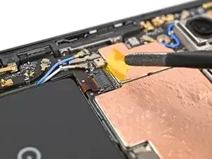
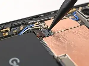
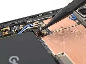
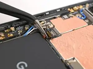
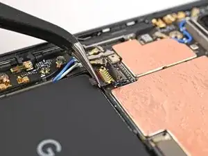
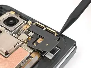
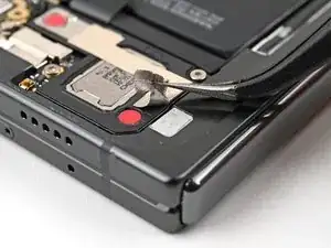
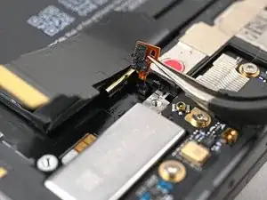
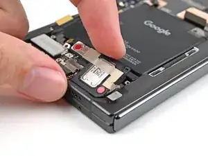
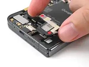
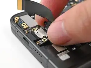
    • Slide one arm of a pair of angled tweezers under the metal neck of the black antenna cable's connector head on the USB‑C board.

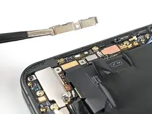
    • Lift straight up to disconnect the cable.

  18. EEV6S1G6s5avKg2Z
    EEV6S1G6s5avKg2Z
    pQdgh1KKmRFFAvGY
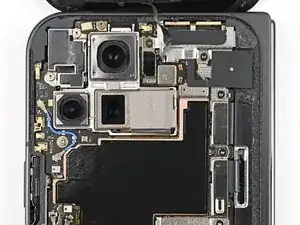
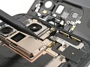
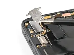
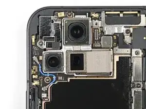
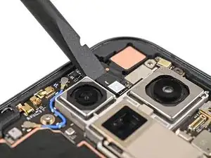
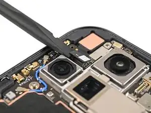
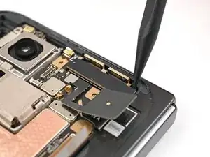
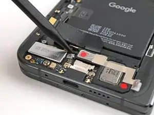
    • Use a Torx Plus 3IP driver to remove the two 2.6 mm‑long screws securing the inner front camera bracket.

  19. wO1GwSCHA1GMKQWS
    wO1GwSCHA1GMKQWS
    StTB3NOubJZdshBS
    tQw1QieFAcrXg5rT
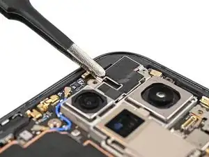
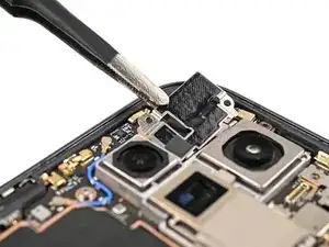
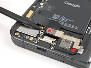
    • Use tweezers, or your fingers, to lift the inner front camera bracket up and toward the left edge of the phone to release its clips.

    • Remove the inner front camera bracket.

  20. 6TUMGHIaYiE2xC2m
    6TUMGHIaYiE2xC2m
    IsKrcDjLnjRGEecA
    • Use a spudger to pry up and disconnect the inner front camera press connector.

  21. d1eks1GCoySR4CNg
    d1eks1GCoySR4CNg
    otv4FxFLQnKPiBIT
    tEusGNyayILsHTIT
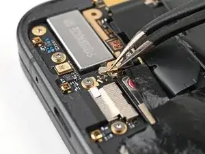
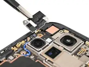
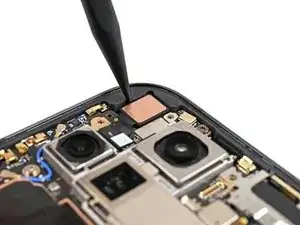
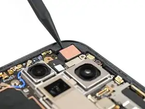
    • Use the point of a spudger to pry up the inner front camera and separate the adhesive securing it to the frame.

    • Remove the inner front camera.

  22. uPXT6rnjYElJ2owM
    uPXT6rnjYElJ2owM
    eJ2XfmMcqmcCFTax
    TdyYX26srvlm6pgS
    • Slide the flat end of a spudger under the ultra wideband antenna to separate the adhesive foam securing it to the frame.

    • Use tweezers, or your fingers, to lift the antenna off the frame to separate any remaining adhesive.

  23. PgVl6XTZbEO6byyR
    PgVl6XTZbEO6byyR
    rkjoSM1DhPdo2Nvj
    • Use a Torx Plus 3IP driver to remove the two 3.0 mm‑long screws securing the ultra wideband bracket.

  24. 6OMUnOPo5qOOHRrM
    6OMUnOPo5qOOHRrM
    KLOEgFMMqLEJItIp
    V3PblC1DbRUqoNQy
    • While holding the ultra wideband antenna out of the way, pull the bracket toward the bottom of the phone to release its clips.

    • Remove the ultra wideband bracket.

  25. YoGQIlTckihCiPnl
    YoGQIlTckihCiPnl
    pdSU6ufMNdSsr1oe
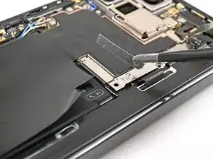
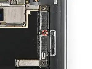
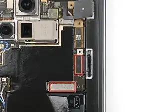
    • Use a Torx Plus 3IP driver to remove the 3.0 mm‑long screw securing the interconnect cable bracket.

  26. 2JJJSWEGjoBHfKGf
    2JJJSWEGjoBHfKGf
    CsbSrODKVDo6y3MO
    VloFmdqCY15K2fZn
    • Use tweezers, or your fingers, to pull the bracket toward the right edge of the phone to release its clip.

    • Remove the bottom interconnect cable bracket.

  27. EZoIrpRC1iwLEGVJ
    EZoIrpRC1iwLEGVJ
    WyV5p52WUMKmCBpY
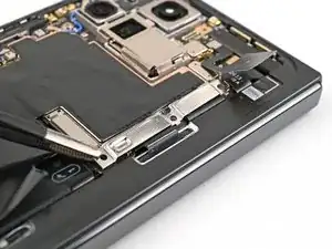
    • Use a Torx Plus 3IP driver to remove the 3.0 mm‑long screw securing the inner display cable bracket.

  28. gwjhicJrEiLnSMa3
    gwjhicJrEiLnSMa3
    mho1B1vmIMJcosDU
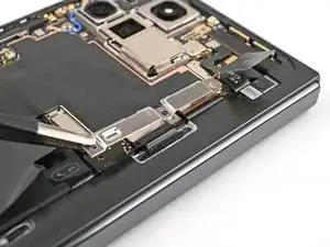
    • Use tweezers, or your fingers, to pull the inner display cable bracket towards the left edge of the phone to release it from its clip.

    • Remove the inner display cable bracket.

  29. ony3KAJfNcJBwbmC
    ony3KAJfNcJBwbmC
    MUmqLTeeVwGWNZoL
    pXckHap1bJYKJw1X
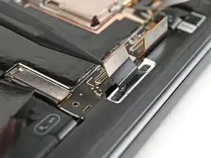
    • Insert the point of a spudger under the bottom left corner of the inner display press connector, next to the gold marker on the logic board.

    • Don't insert your spudger anywhere else, as you risk dislodging surface‑mounted components.

    • Pry up and disconnect the inner display cable.

  30. PHDgwUJXhlNIppJ1
    PHDgwUJXhlNIppJ1
    c56Iwpm3TpMpwDHd
    NUHUgKTTjmuDTAQK
    • Repeat the previous step to disconnect the top and bottom interconnect cable press connectors, making sure to only pry next to the gold markers.

  31. xgauuMQiwuivsBPM
    xgauuMQiwuivsBPM
    s6tyEaHjlFqCKaFj
    • Peel the graphite sheet off the bottom speaker to separate the adhesive securing it.

  32. 5wCH1LXTQtNSoupP
    5wCH1LXTQtNSoupP
    qqeZKuHvBjFFTvWl
    brvCZNDNIQWBUI46
    • Continue peeling the graphite sheet off the logic board to separate the remaining adhesive.

  33. JSKpMCPKAF3ZZxet
    JSKpMCPKAF3ZZxet
    IIluypQeWBTQGpvL
    • Use tweezers, or your fingers, to peel off the yellow tape on the side button cable ZIF connector.

    • Set the tape aside. You'll need it during reassembly.

  34. 5DvRl2dna6ZBZ1rd
    5DvRl2dna6ZBZ1rd
    W1NcMdKoQWU5wbOp
    • Use the point of a spudger, or your fingernail, to lift the locking tab on the side button cable ZIF connector.

  35. MKyJZFKamF461Whg
    MKyJZFKamF461Whg
    iqibbttnfLpPi3al
    • Use angled tweezers to pull the side button cable straight out of its slot.

    • Take care not to puncture the battery—it can leak dangerous chemicals and/or catch fire.

  36. 5bFa5kfIQXqUlrnO
    5bFa5kfIQXqUlrnO
    JfkDRtGR5twVTKQ5
    • A thermal pad lightly adheres the 5G mmWave antenna to the frame.

    • Use the tip of a spudger to pry up the 5G mmWave antenna from the frame and separate it from the thermal pad.

  37. TEoUBKNyUsLn4Ks6
    TEoUBKNyUsLn4Ks6
    bUaXgrbZNF5YmyIE
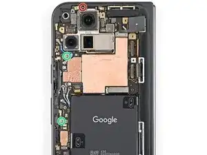
    • Use a Torx Plus 3IP driver to remove the three screws securing the logic board:

    • One 2.2 mm‑long screw

    • Two 2.6 mm‑long screws

  38. YPRmZRWPNPJ61VBW
    YPRmZRWPNPJ61VBW
    eDsYU3nsJJwWZBEZ
    GsMp5mruIEBfDsSb
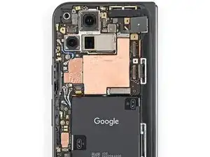
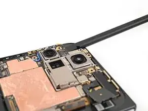
    • Insert the flat end of a spudger under the top left corner of the logic board, next to the inner front camera cutout.

    • You might feel some resistance since the logic board is bonded to the frame by thermal paste.

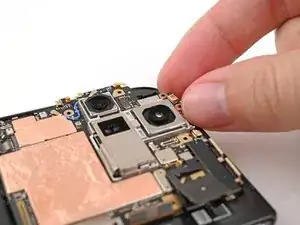
    • Pry up the logic board enough so you can grip the top edge with your fingers.

  39. LkZTftFlDZIaBeAy
    LkZTftFlDZIaBeAy
    DeLGHP3eyMsjKUn3
    OjDrOg5coS5LriPo
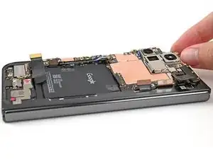
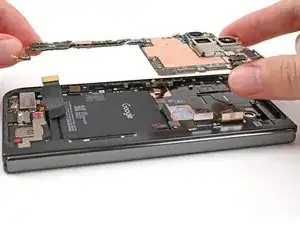
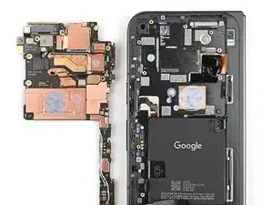
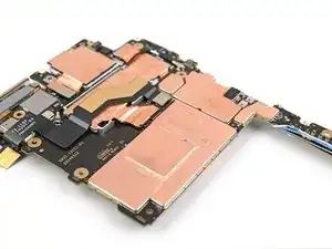
    • Lift the top of the logic board out of the frame and remove it.

    • Lay down the logic board upside down on a clean surface.

  40. XZTwDNDLdkuaNnIG
    XZTwDNDLdkuaNnIG
    A5TW5XopRcvb1DLO
    DmPQRiGFfjKZIGBR
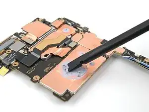
    • Use the flat end of a spudger to scrape away large pieces of old thermal paste from the frame.

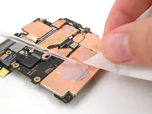
    • Apply a few drops of highly-concentrated isopropyl alcohol (over 90%) to any remaining thermal paste residue.

    • Wipe away the residue using a coffee filter or lint-free cloth.

  41. 3S5EFlGVWNtMWuyg
    3S5EFlGVWNtMWuyg
    jT4Q211K5rVaYTSy
    TXGGS5nH3mjOiqCV
    • Don't press down heavily on the logic board while cleaning it to prevent bending the metal springs or smudging the rear camera assembly.

    • Repeat the thermal paste cleaning procedure for the bottom of the logic board.

  42. ZANVo6vSZcaB4lGD
    ZANVo6vSZcaB4lGD
    hDUyZQSRiNuONlJw
    Zc11DLbUDvsoScfe
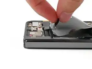
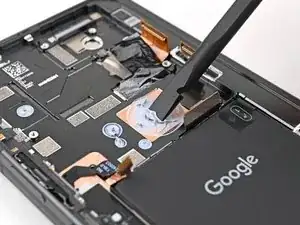
    • Use tweezers, or your fingers, to peel the section of conductive fabric connecting the loudspeaker to the frame.

  43. CkEIBKyIlNVPH13G
    CkEIBKyIlNVPH13G
    HTHngt5Y1WMcvoS1
    iykZltlHuIxgvjQ2
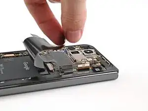
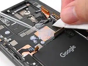
    • Slide one arm of a pair of angled tweezers under the contact pad connected to the loudspeaker.

    • Take care not to puncture the battery—it can leak dangerous chemicals and/or catch fire.

    • Lift the contact pad to separate the adhesive securing it to the frame.

  44. SLMfyyilRpELLHPc
    SLMfyyilRpELLHPc
    vEXK4yxTh5kjRstE
    • Use a Torx Plus 3IP driver to remove the 2.6 mm‑long screw securing the loudspeaker.

  45. EVHI4cNKampKrtaN
    EVHI4cNKampKrtaN
    dtghH1RPAnqbiiER
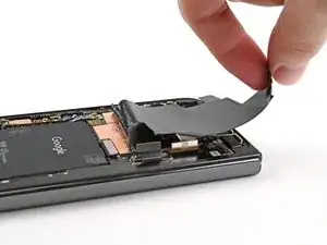
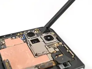
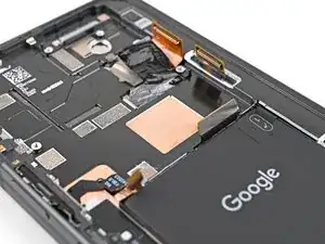
    • Use the tip of a spudger to pry up the left edge of the loudspeaker to separate the adhesive securing it to the frame.

  46. HUUyBZ2YAJtViBwH
    HUUyBZ2YAJtViBwH
    2MiJUGrVflLcRtP5
    1iXKuIrhFo1qn4xv
    • Use your fingers to lift the top edge of the loudspeaker and pull it out of its recess in the frame.

    • Remove the loudspeaker.

  47. kFWUmHdUoXk1bu23
    kFWUmHdUoXk1bu23
    k2B25hW1RueTXKLu
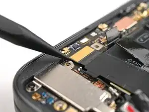
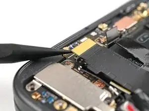
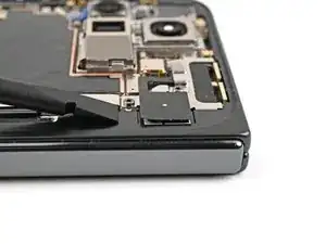
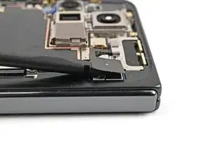
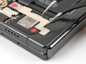
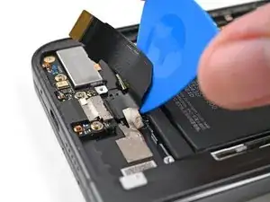
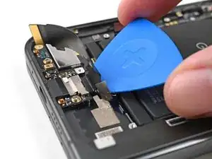
    • Slide the tip of an opening pick under the USB-C port board cable to separate the adhesive securing it to the frame.

  48. Bklx61PCLM1kL1I4
    Bklx61PCLM1kL1I4
    eFIpOhvjYC4hONbv
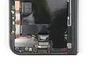
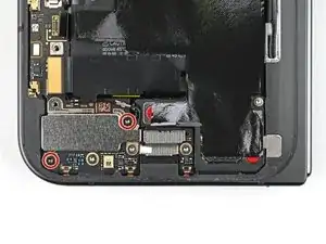
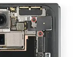
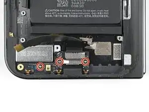
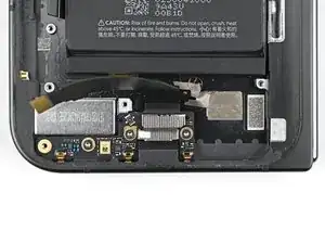
    • Use a Torx Plus 3IP driver to remove the three 2.6 mm‑long screws securing the USB-C port board.

  49. Iht3dsj6RTICLRQq
    Iht3dsj6RTICLRQq
    mILTfNBB3AcSC2GD
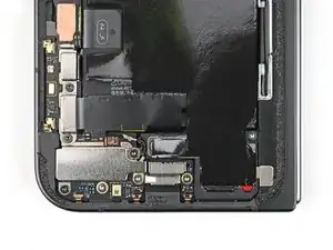
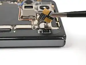
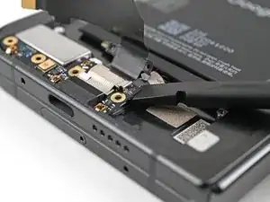
    • Use a spudger to pry up the top right corner of the USB-C port board to unclip it from the frame.

  50. EmToRhGseqRcLOlZ
    EmToRhGseqRcLOlZ
    TDuNuJXvvdoJgP4N
    • Pull the USB-C port board out of its recess in the frame and remove it.

Conclusion

Take your e-waste to an R2 or e-Stewards certified recycler.

Compare your new replacement part to the original part—you may need to transfer remaining components or remove adhesive backings from the new part before you install it.

To reassemble your device, follow these instructions in reverse order.

Repair didn’t go as planned? Try some basic troubleshooting, or ask our Google Pixel 9 Pro Fold Answers Community for help.

Alex Diaz-Kokaisl

Member since: 16/01/22

151892 Reputation

0 comments