
Introduction
Before attempting to disassemble the TS101, strongly consider not doing it.
The sole circuit board in the iron is soldered directly to the display's integral ribbon cable, and the display is glued into place, meaning that it's effectively impossible to disassemble to a reasonable degree without invasive methods and damage is a strong possibility.
Definitely read through these instructions before starting.
-
-
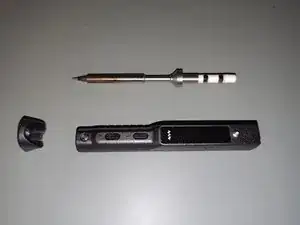
First remove the soldering tip and the anti-slip cap.
-
Leave the tip retention screw and the grounding screw in place. Neither will be relevant to the disassembly.
-
In particular, the grounding screw retains its sleeve and is very hard to get back in place.
-
-
-
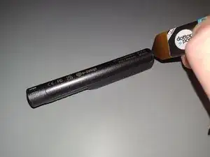
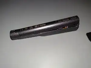
Pry the end of the case panel up, just enough to disengage the clip there. This is the end by the power inputs.
-
Pry both sides of the case panel up, angling the panel from the remaining end.
-
Pull the case panel away, along the length of the case, pulling the tab on the end of the case panel out of the case.
-
(A fingernail is a sufficient tool for this task.)
-
-
-
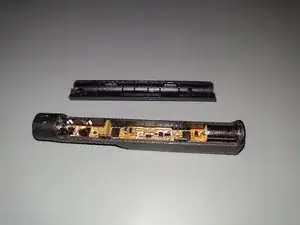
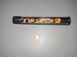
Remove the separation panel. It just slides into slots in the case.
-
Note the orientation of the panel. Which way it faces probably doesn't make any difference, but it's definitely not going to hurt to put it back in the same way.
-
On mine, the printing and the solder traces were facing the tip side.
-
-
-
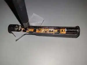
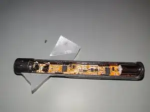
Place some tape on the buttons or otherwise retain the buttons to prevent them from getting loose inside the case.
-
I burnished the tape against the top of the buttons to ensure adhesion.
-
-
-
There is a single mounting screw, near the soldering tip power clamps. A Phillips 000 but worked the best for me, but a Phillips 00 worked well enough.
-
-
-
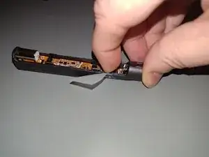
Push the entire circuit board towards the tip side. There's a leaf spring making ground contact with the tip mounting ring, so you'll be pushing against light spring pressure.
-
The ground screw sleeve slots into the circuit board and may prevent you from shifting the circuit board. Lift up slightly on the power input end to disengage it. It probably needs to be lifted less than a millimeter.
-
I was sometimes able to lift the power input side of the circuit board by just pressing down on the opposite side. If not, try pushing up on the power connector through the case with a narrow tool.
-
Lift the power input side of the circuit board all the way out of the case. You'll need to push the circuit board towards the tip side with significant force. I think some very slight bending of the circuit board is required to get the USB-C socket past the flanges of the case.
-
-
-
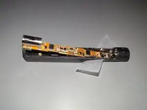
Unfortunately, this is as far as I got without damage.
-
At this point, the power input side of the circuit board is out of the case, but the tip side is still in, blocked by a few millimeters worth of case overhang.
-
It's very hard to see, but the circuit board is also being held by the the display's integral ribbon cable, which has been soldered directly to the bottom side of the circuit board.
-
If you want to continue, I think you'd have to remove the display's glass(?) panel from the case, which is almost certainly glued in.
-
If you can get the glass out, I think that the actual display is just trapped between the glass and the case and should be able to be rotated up and slid through a slot in the case.
-
I gave up at this point, but, in trying to get the ground screw sleeve and one of the buttons back in place, I managed to snap the ribbon cable off of the display.
-
-
-
Just to the right of the ground screw sleeve you can see the far edge of the display panel, and just to the left of the buttons you can see the other edge of the panel with the remnants of the ribbon cable, with a solid piece of the case covering the middle of the panel.
-
The panel itself will shift slightly in that space, so it seems like the display itself is not glued down. Again, if you removed the glued-down(?) glass panel covering the display, it probably would allow you to lift the far end and allow the display to slide through the slot where the ribbon cable is/was.
-
-
-
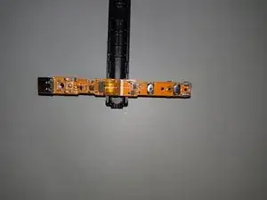
Here is the top side of the circuit board, with the ribbon cable folded in both directions to allow visibility to what's underneath it on both sides.
-
(The case panel was used here just to prop up the circuit board.)
-


To reassemble your device, stop before you break the display's ribbon cable, then follow these instructions in reverse order.
2 comments
Hi. i would like to ask what chip does the TS101 uses because i dont want to destroy my TS101 and on the photo i cant properly ead it so if you provide the number or even better some datasheet it would be amazing! thank you
Zmetek77 -
The microcontroller? Assuming the IronOS docs aren't lying, it's an STM32F103T8.