Introduction

If the machine can no longer be switched on, the power board may be defective. Most often, the components of the switching power supply are burned out. The parts are not expensive, a repair attempt is worthwhile. You have to be able to solder/desolder pretty well though, we have a guide for that.

The parts are quite easy to get in any electronics store, especially you need a resistor 47 Ohm, 3W, an inductor 1mH and an IC LNK364GN.

  1. gGp2mPtSZjLFUs4E
    • Unplug the power cord!

    • Remove all attachments such as water tank, pulp drawer, brew group.

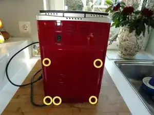
    • Turn the machine with the back facing you.

    • Remove five Torx T20 security screws.

    • A small hurdle: These screws have a pin in the middle, so the screwdriver must have a hole.

    Screwdriver must have a hole? What does that mean? Is it a standard Tx20 bit?

    Kevin -

    No, it is a TR20 Security Bit, which really has a hole (if you look to the star shape) . See TR10 Torx Security Screwdriver

    VauWeh -

    Bits from iFixit are equipped with it.

    VauWeh -

  2. BnoacoHxc6HQr1YS
    BnoacoHxc6HQr1YS
    RiGlr1amJrHguDl2
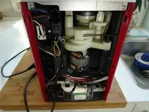
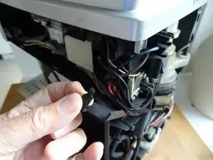
    • Lift out the back.

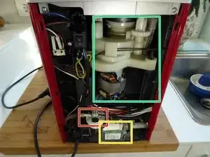
    • The following components are immediately visible:

    • grinder

    • pump

    • flowmeter

    Sehr gute Anleitung. Die Security Schrauben der Rückwand können auch durch normale Kreuzschlitzschrauben ersetzt werden. Natürlich mit gleichen Abmessungen. Es erleichtert bei späteren Reparatur Arbeiten die Werkzeuge Auswahl , da überall Kreuzschlitzschrauben verbaut sind.

    Willi Greubel -

  3. dm44GwGUppKOfExQ
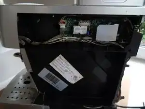
    • Also slide the cover - if not already done - on the water tank side backwards and remove it.

  4. IbqYOc51nDQFIBDc
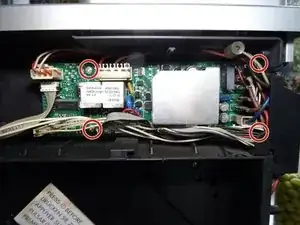
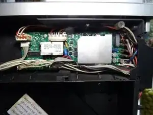
    • The power board is located under the cover. It is fixed with four screws in the corners and connected with a lot of cables.

    • Move the cables a bit to the side and unscrew the four Phillips screws in the corners.

  5. DNdRO2KyS6DX2xw1
    DNdRO2KyS6DX2xw1
    Qu2UqPyHG2MnFp3J
    • The cables have many different connectors and can almost not be confused. Make a special note of where the flat connectors are connected.

    • The flat connectors can be disconnected more easily if you lift the cover in the corner of the device to the side.

    • Lift the board out a few centimeters.

    • Carefully loosen all connections. Some are secured with latches that you have to push away first.

  6. POoXkHANm5pDHUVj
    POoXkHANm5pDHUVj
    wHwsGTyDUNNjkFPr
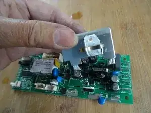
    • Here is the power board. The aluminum heat sink is only attached to the back of the board with three tabs. Straighten the three tabs with pliers and lift out the heat sink. Make sure it is clamped to a triac.

    • When reassembling, make sure that you have applied enough thermal paste.

  7. uHvLw4dH4GVuXNUQ
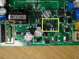
    • Here are the critical components:

    • R55: Resistor, 47 Ohm, 3 W

    • L1: Inductance 1mH

    • U1: Switcher IC LNK364GN

  8. pDZDVCur4ZoCgFNw
    pDZDVCur4ZoCgFNw
    mJEkXkWvJ1omD3XB
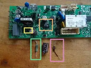
    • First desolder these three components. Use a desoldering suction pump and/or desoldering wire. The desoldering of the IC is tricky, it is a SMD version. It's easier if you desolder the capacitor C3 beforehand as well, maybe you can also cut the pins of the IC carefully.

    • Check the components:

    • On this board, the inductor L1 was clearly defective, it was black, yellow beads were sweated out, the resistance was much too high, it should be in the range of 3 ohms.

    • The 47 Ohm resistor R55 was infinite - nothing can work like that.

    • The IC LNK364 was probably the trigger of the defect, between the two pins with the big gap the resistance should be some MegOhm, it was only a few Ohm.

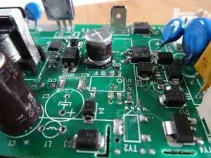
    • Check also the diode D1 (in installed condition), it should conduct only in one direction. If defective, replace it with a 1N4005. (Cathode, so minus in direction L1).

    • Solder everything back in and drink a coffee first... other components could be defective as well...

Conclusion

Work through the steps in reverse order to reassemble your device.

VauWeh

Member since: 19/10/15

234462 Reputation

16 comments

Hallo die Anleitung, passt im wesentlich auch zur ECAM 23 450S - die Platine sieht etwas anders aus - man muss kein Kühlblech demontieren, die Bauteile tragen die gleichen Nummern / Bezeichnungen. Nach dem Wechsel läuft unsere Minna wieder. Danke - auf die nächsten 12 Jahre.

A. Weber -

Freut mich, Grüße.

VauWeh -

Hallo,

ESAM 3600, die Platine ist auch anders die baustein Bezeichnung ist gleich.

Reparatur hat dank Anleitung bestens geklappt.

Danke

LG Dieter

Dieter Stach -

Interessante Info, danke. Freut mich, dass es geklappt hat.

VauWeh -

Thank you for sharing! Had the same problem with mine, thanks to your guide I could repair the board and the machine works well as before. Nice!

Robert

Benedikt Robert Hajas -

I'm glad to hear that. Another machine saved. Repair is war on entropy!

VauWeh -
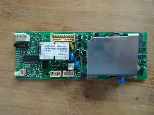
Below the two white relays there's a component on Q1. Can you or anyone else help me find out what that is? Mine is blown and unidentifiable, I assume Q2 is probably the same but Q2 is unpopulated on my board so I have nothing to compare with.

John D'oh -

Is there really a relay? Perhaps this page helps, they tried a reverse engineering for ESAM.

VauWeh -

Thank you for the reply. Yes what I refered to is the two white relays, that usually have a sticker with the board part number and software version on top of them.

In the meantime I may or may not have found some useful information for me and anyone else needing to diagnose and repair these boards. There are a some variance between machine models, but that appears to mostly be software and which components are populated, not so much different components.

In my case, it seems Q1 and Q2 is an SOT-23 packaged P-channel FET. Component CHT2301PT (this is discontinued) or TSM2301. Alternatively, PNP Resistor Equipped Transistor: PDTA143ET.

I'm pretty sure it's a not allowed to share scematics or links to such material on Ifixit. But lets instead imagine for a moment; some hypothetical Oogle might reference something called "delonghi_ecam_21.116_21.117_22.110_parts_schema_pcb" as a source of... useful information :)

John D'oh -

@prollie do you mean the document on the bottom of this page DeLonghi ECAM Series Nice find. It'll be a lot easier to keep it here than to have to go through a search engine and all that stuff. This way people can focus on helping you instead of hunting for it :-) You got the iFixit Guru @vauweh working on it so you know it'll be resolved :-) Repair is War on Entropy!

oldturkey03 -

@prollie @oldturkey03 Well - this fault ist unknown to me and I appreciate the link! I hope that replacing the parts is the right solution. Otherwise there ist another possibility (for european users): When I had issues like yours, they did the job.

VauWeh -

I have same problem with my coffee machine. I have made quick lookup with schematic and multimeter and everything looks fine expect U1 - LNK364GN. it seems strange to me that only U1 would be at fault and it would be enough to replace only U1. Why is it destroyed? Any suggestions?

Jaromir Hurek -

Your post and question is unclear. "Have the same problem"

= Will not power on?

"it seems strange to me that only U1 would be at fault and it would be enough to replace only U1"

= you replaced this IC, and that was enough to fix it? If not, are you certain that this is the only failed component? Or are you unsure if there could be more rhat you may have missed?

It's not guaranteed always the case, but this IC very often fail together with the big 3W resistor and the choke (?) right next to it. These can fail from power spikes, so there's also fuses to check. Do also inspect the traces(!) thoroughly on both sides. In a few instances, I have seen some of the small traces on the back of the board completely burnt off; detached from the board substrate and curled up.

Depending on how bad, that can take some time to fix but it's not complicated. If a trace is severely blown like this and you reconstruct it, remember to also check that none of the vias along that trace have also gotten burnt off.

John D'oh -

Beim Zusammenbau ist mir aufgefallen, daß es eine Verwechslungsmöglichkeit gibt: Die beiden 2-poligen weißen Stecker mit der Bezeichnung 16 und 17 ,an der linken Platinenseite (im Kontakt J6 und J12) könnten vertauscht werden, alle anderen Steckverbinder sind eindeutig zuordenbar. Wie ist es richtig , Stecker 16 oben an J6, und Stecker 17 unten an J12 oder gerade andersrum?

Günther -

@guenther13523 Im Moment weiß ich das auch nicht, es steht aber wahrscheinlich hier, ganz am Ende der Link zum Service Manual.

VauWeh -

J6 ist der Stecker zum Thermosensor, da müssten so steife weiße Kabel hinführen.

VauWeh -