Introduction
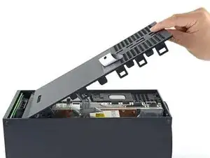
This guide shows how to removal the center chassis in your Xbox Series X. This guide has the power supply still attached, which reduces the amount of steps needed for a motherboard replacement or SSD removal.
-
-
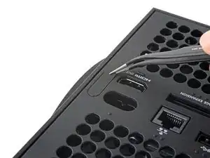
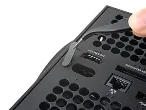
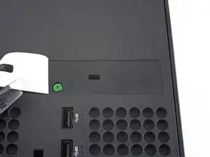
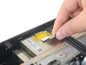
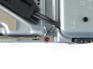
Use a pair of tweezers to remove the sticker hiding the first screw on the back panel, near the base.
-
-
-
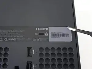
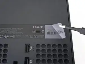
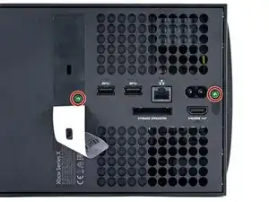
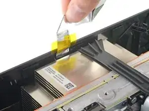
Use a pair of blunt tweezers to peel back the large sticker on the back panel to reveal the second screw.
-
-
-
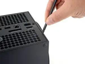
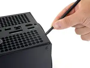
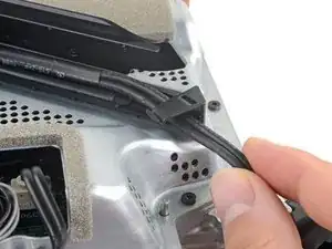
Insert the flat end of a spudger into the gap between the back panel and the shell, near the left side of the base.
-
Pry up the back panel to release it from the locking clips.
-
-
-
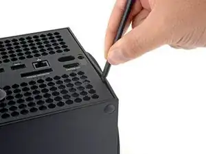
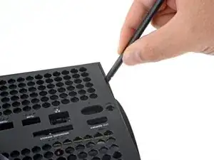
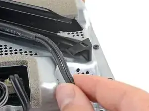
Insert the flat end of a spudger into the gap between the back panel and the shell, near the right side of the base.
-
Pry up the back panel to release it from the locking clips.
-
-
-
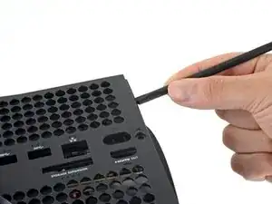
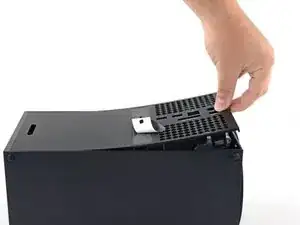
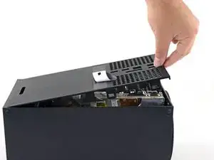
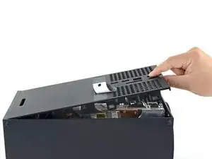
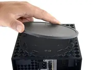
Grip the back panel at the opening you just created and pull it up and away from the shell to unclip the long edges.
-
-
-
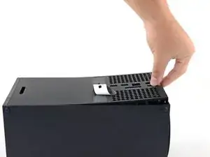
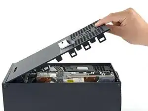
Tilt the back panel up and pull it away from the top edge of the shell to release it from the gap.
-
Remove the back panel.
-
-
-
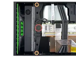
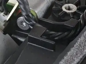
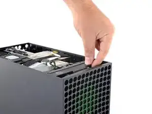
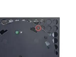
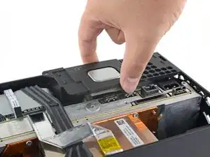
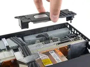
Use a T8 Torx driver to remove the three screws securing the fan to the center chassis:
-
One 10.5 mm pancake screw
-
Two 8.8 mm screws
-
-
-
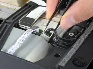
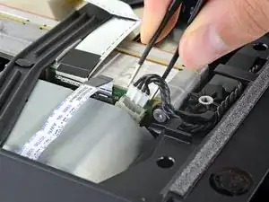
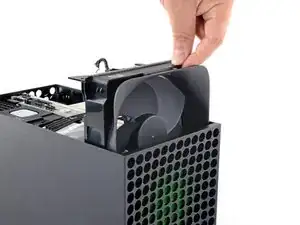
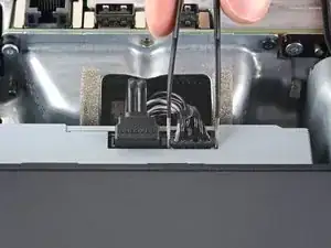
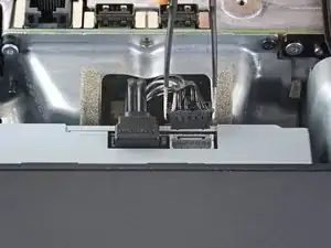
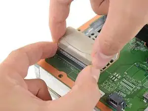
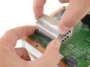
Use your fingers or a pair of blunt tweezers to grip the edges of the fan cable connector, and pull up to disconnect it from the center chassis.
-
-
-
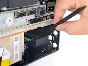
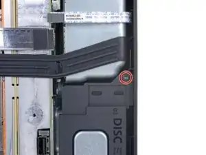
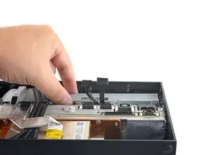
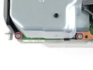
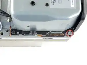
Use a T8 Torx driver to remove the two 8.8 mm screws securing the optical drive's vibration isolator to the shell: one on the base and one on the top of the isolator.
-
-
-
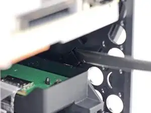
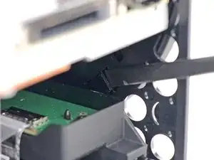
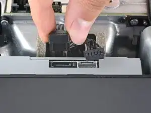
Use a pair of blunt tweezers to grip the edges of the optical drive power connector and pull up to disconnect it from the optical drive.
-
Use your fingers to pull up and disconnect the data cable from the optical drive.
-
-
-
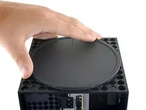
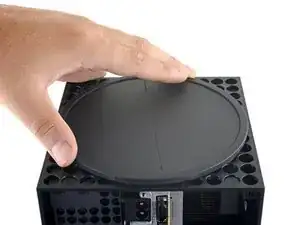
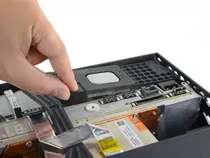
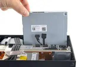
Grip the top edge of the optical drive and pull it out of its slot in the shell to remove it.
-
-
-
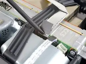
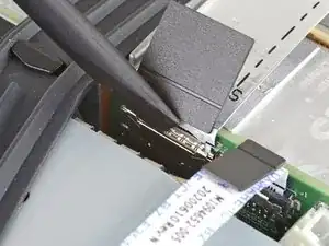
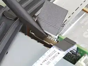
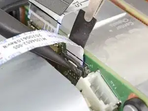
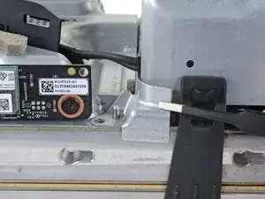
Use the flat end of a spudger to flip open the metal locking tab on the USB port ribbon cable.
-
-
-
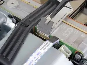
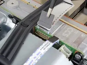
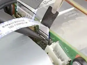
Use a pair of tweezers to pull up on the black plastic pull tab to disconnect the USB port cable.
-
-
-
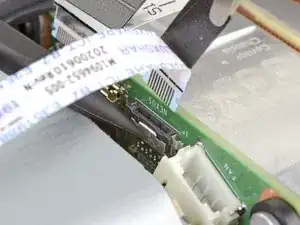
Use the pointed end of a spudger to depress the metal tab on the side of the power button cable's board connector.
-
With the metal tab depressed, use a pair of tweezers to pull up on the pull tab to disconnect the power button cable from the center chassis.
-
-
-
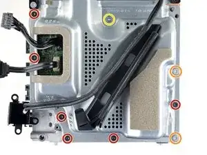
Use a T8 Torx driver to remove the three 7.4 mm screws securing the center chassis assembly to the shell.
-
-
-
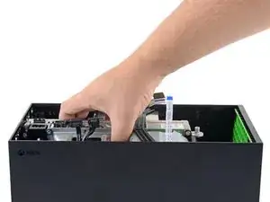
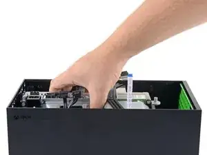
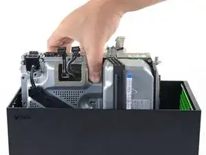
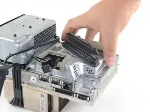
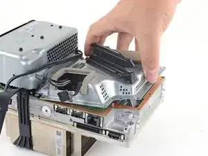
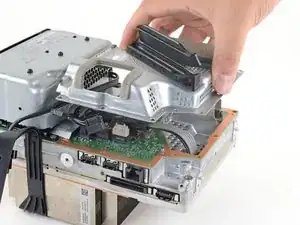
Grip the center chassis and pull it towards the green fan grille at the top of the shell, uncoupling the guide pegs from the shell.
-
Lift out the center chassis assembly to remove it from the shell.
-
-
-
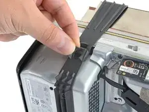
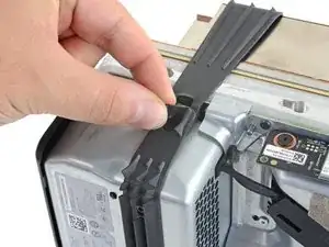
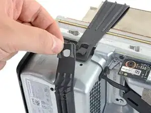
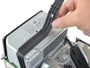
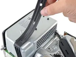
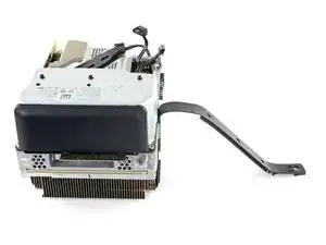
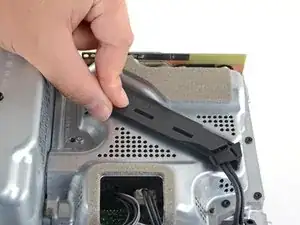
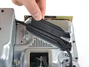
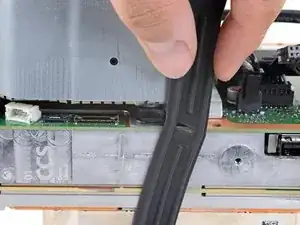
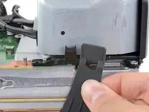
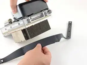
Pull the chassis strap over and off of the power supply.
-
Once the strap is off of the power supply, set the loose section to the side.
-
-
-
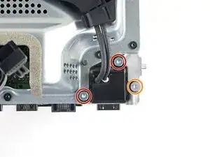
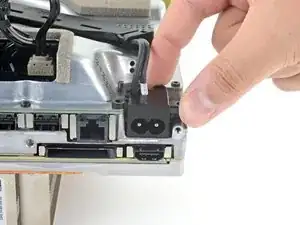
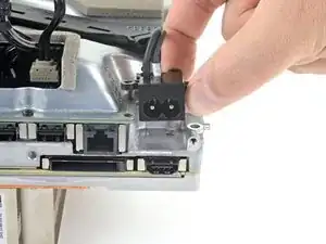
Use a T8 Torx driver to remove the three screws securing the power cable port to the chassis:
-
Two 13.1 mm screws
-
One 35 mm screw
-
-
-
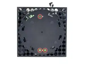
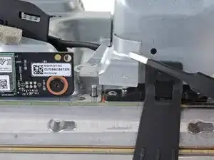
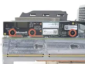
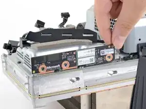
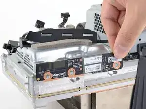
Use a T8 Torx driver to remove the three 9.6 mm screws securing the accessory antenna board to the center chassis.
-
-
-
Use a T8 Torx driver to remove the nine screws securing the board shield:
-
Six 8.8 mm black screws
-
Two 35 mm silver screws
-
One 13.1 mm silver screw
-
-
-
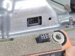
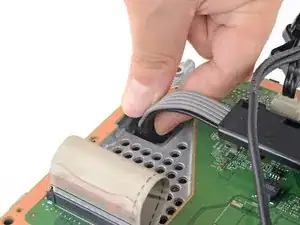
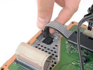
Grip and compress the locking tab on the 10-pin power connector.
-
While compressing the locking tab, lift the connector straight up to disconnect it from the board.
-
-
-
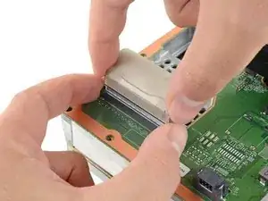
Grip the base of the interconnect cable connector with your fingers.
-
Depress each side of the connector to unlock the cable locking tabs.
-
With the locking tabs depressed, grip the edges of the interconnect cable and pull it straight out of the connector to disconnect it.
-
-
-
Use a T8 Torx driver to remove the three 35 mm‑long silver screws from the power supply—leave the fourth black screw in place.
-
-
-
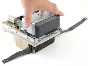
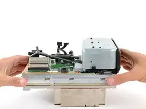
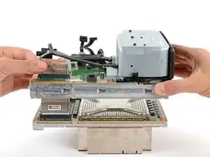
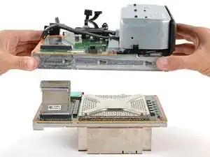
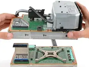
Grip the edges of the center chassis (not the power supply) and lift it off of the motherboard and heatsink assembly, routing the interconnect cable through its cutout.
-