Introduction
This guide will show you how to partially disassemble this lens to be able to replace the Zooming Key. There will also be a number of other parts which locations, how to remove them, and how reinstall them will be shown during this guide. Notable parts include the Main PCB Assembly and the IS Lens Assembly.
A dust blower is recommended to blow dust off of any internal lens elements or parts during this process. Additionally, a clean microfiber cloth is good to have incase you accidentally touch any of the internal lens elements and need to clean off your fingerprint from the lens.
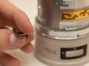
Finding a replacement zooming key:
At the time of making this guide, I could not locate anywhere to buy a replacement zooming key for this lens, with the part number YA2-4750. I ended up discovering that the zooming key of a Canon EF 70-200mm f/2.8L USM lens could work (the non-IS version of this lens), which has a part number of YA2-2054. I took this part out of a broken lens, but I also did find that part available online for purchase.
It's important to note that the part is not a perfect fit though. The alternate zooming key extends exactly 1mm too far to fit. However, I was able to grind it down using a dremel and an aluminum oxide grinding wheel. After grinding it down 1mm, it was a perfect fit.
-
-
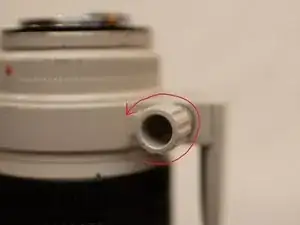
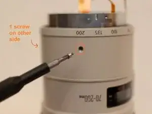
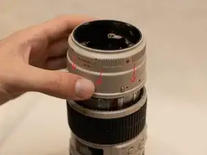
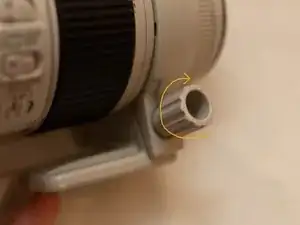
Loosen the knob on the tripod mount.
-
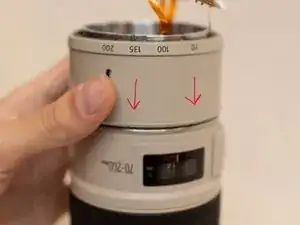
Rotate the tripod mount counter-clockwise approximately 135 degrees.
-
Pull the tripod mount towards the rear of the lens. If it does not immediately come off, rotate the tripod mount back and forth slightly until it is in the correct position for the tripod mount to detach from the lens.
-
-
-
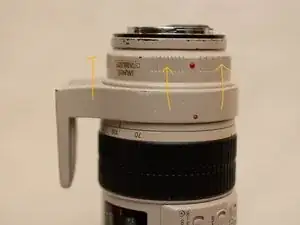
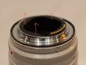
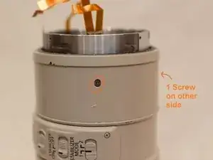
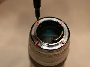
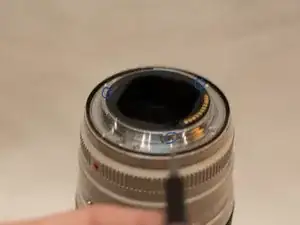
Unscrew the 5 screws around the inner part of the lens mount.
-
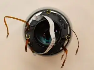
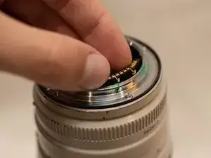
Carefully pull up around the inside edge of the back cover (the black plastic piece inside of the lens mount). The cover should be able to pop out without too much force.
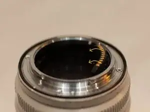
-
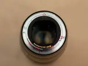
Gently push the electrical connector away from the lens mount, so that it is resting off of the lens mount.
-
-
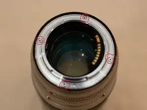
-
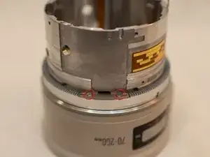
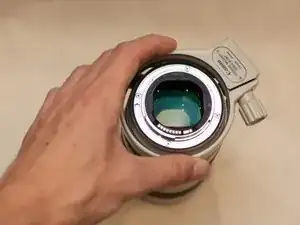
Unscrew the 4 screws holding in the metal lens mount.
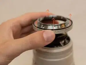
-
Grab the metal ring directly below the lens mount and pull upwards. It is best to keep the metal ring, the lens mount, the lens mount washer, and the weather seal together as taking them apart is not needed.
-
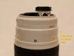
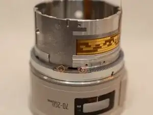
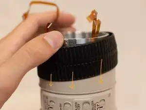
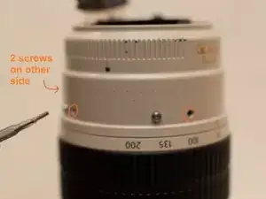
Next, remove 4 screws around the outside of the fixed barrel assembly.
-
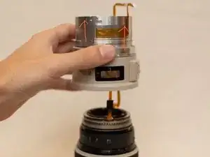
Pull the fixed barrel assembly directly upwards.
-
-
-
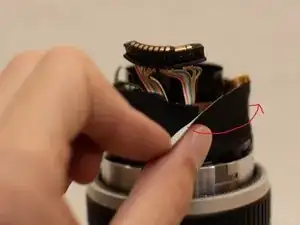
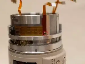
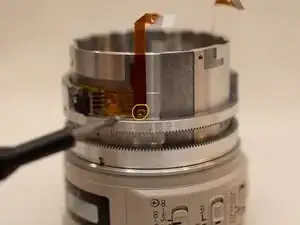
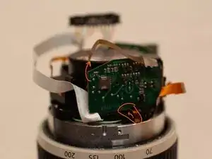
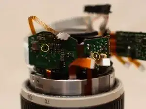
Peel up the end of the black tape surrounding the main PCB assembly and very slowly and carefully begin to peel back the tape.
-
Watch out for ribbon cables that the tape may be adhered to. If needed, grab the ribbon cable with a pair of blunt tip tweezers as you peel back the tape.
-
Set the tape aside, as it will be placed back during reassembly.
-
-
-
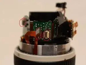
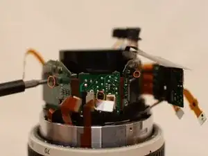
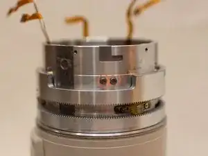
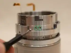
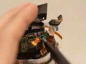
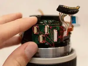
Carefully disconnect the 7 ribbon cables from the main PCB boards.
-
Unscrew the 3 screws holding the PCB boards in place.
-
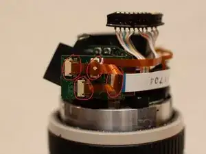
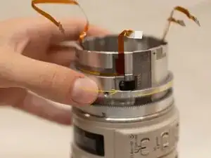
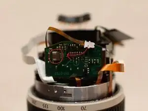
Pull off the black plastic cover.
-
Carefully pull off and set aside the main PCB boards.
-
-
-
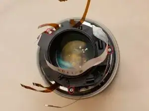
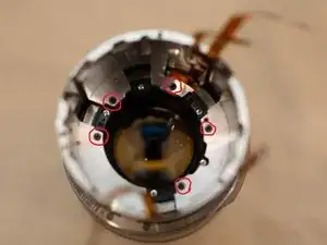
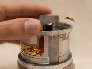
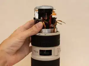
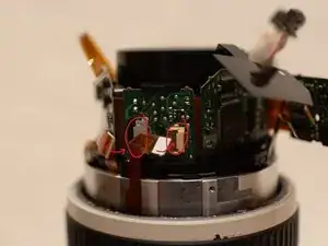
Unscrew the 3 silver screws around the outside edge of the IS lens assembly.
-
Carefully pull the IS lens assembly up and out of the lens. Be careful not to snag any of the ribbon cables.
-
-
-
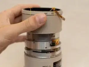
Slip a pair of tweezers underneath the rubber zoom grip and work around the grip to get it over the edge of the zoom ring.
-
Continue until the grip is in a position to be able to pull/push it the rest of the way off the lens with your hands.
-
Remove the 2 screws that are underneath where the zoom grip was. There is one on each side.
-
Pull the zoom ring straight up and off of the lens.
-
-
-
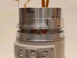
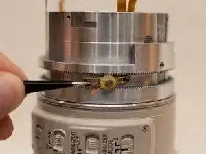
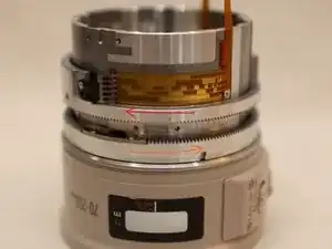
Remove the 2 screws holding in one of the reverse gears.
-
Use a pair of tweezers to pull off the reverse gear.
-
Repeat the previous 2 instructions to remove the other two reverse gears.
-
-
-
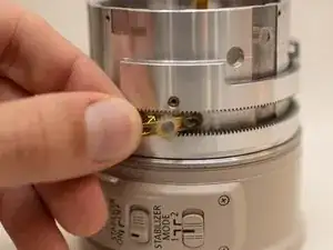
Remove the screw holding the zoom ribbon cable in place.
-
Remove the 2 gear limit screws.
-
Rotate the gear ring 1 as far counter-clockwise as you are able to.
-
Pull the gear ring up and off of the lens. You may need to wiggle the ring slightly if it is having troubles coming off.
-
-
-
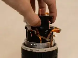
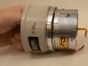
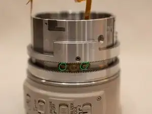
Unscrew the 5 screws holding the intermediate barrel in place.
-
Pull the intermediate barrel up and off of the lens.
-
Set aside the front portion of the lens (that you removed the intermediate barrel from).
-
-
-
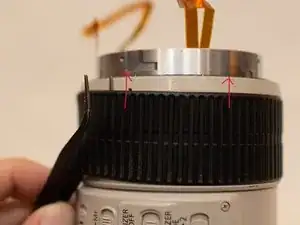
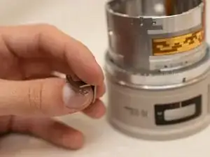
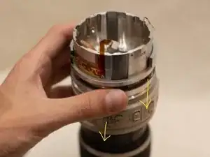
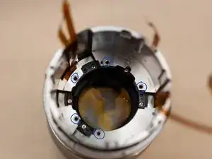
Remove the 2 screws holding in the zooming key.
-
Reach inside of the intermediate barrel with your hand and pull out the zooming key.
-
-
-
Reach inside of the intermediate barrel and position the zooming key in place.
-
Screw in the 2 zooming key screws.
-
-
-
Position the gear ring above the intermediate barrel as you have removed the gear ring, otherwise the ring will not fit into place.
-
Lower the gear ring onto the intermediate barrel and then rotate the gear ring clockwise until the zoom brush is back over the ribbon cable.
-
Screw in the zoom ribbon cable screw.
-
Screw in the 2 gear ring limit screws.
-
-
-
Rotate the upper gear ring (the one you just installed) as far clockwise as you can
-
Rotate the lower gear ring as far counter-clockwise as you can.
-
Insert one of the reverse gears into position, using caution to not move the gear rings.
-
Screw the 2 screws into the reverse gear.
-
Repeat the previous two instructions to install the other 2 reverse gears.
-
You may now move the gear rings to ensure they move smoothly.
-
-
-
Rotate the upper gear ring fully clockwise.
-
Hold the intermediate barrel above the front portion of the lens and feed the 2 long ribbon cables up through the intermediate barrel.
-
Lower the intermediate barrel into place.
-
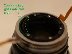
The zooming key should go into the slot on the front part of the lens.
-
Line up the screw holes on the intermediate barrel and the front of the lens. Also make sure to line up the ribbon cables with the cut outs in bottom of the intermediate barrel.
-
Screw the 5 screws into the bottom of the intermediate barrel, locking it onto the front of the lens.
-
-
-
Place the zoom ring into place. The two screw holes should line up with the screw holes on the upper gear ring. The numbers on the zoom ring should be on the side of the lens with the focus window.
-
Screw in both of the zoom ring screws.
-
Slide the rubber zoom grip into place.
-
-
-
Position the IS lens assembly over the intermediate barrel. The spot that the white cable comes out of the IS assembly should be positioned just left of the focus window.
-
Lower the IS assembly all the way down into the intermediate barrel.
-
Screw in the 3 screws to secure the IS assembly into place.
-
-
-
Position the main PCB assembly into its place, being careful of the ribbon cables.
-
The one ribbon cable next to the white cable should be routed underneath and around the backside of the PCB board.
-
Screw in the screws for the left 2 PCB boards.
-
Position the black plastic cover in place. The hole in the ring on the cover should be lined up with the screw hole of the right most PCB board.
-
Screw in the right most PCB board, making sure the screw goes through both the PCB board and the plastic cover behind the board.
-
-
-
Reconnect all 7 ribbon cables to the main PCB boards.
-
Take the black tape from earlier, and slowly wrap it back around the main PCB assembly.
-
The rectangular plastic cover should lay in between the right most PCB board and the PCB board that hangs off of the assembly.
-
-
-
Lower the fixed barrel over the main PCB assembly, lining up the holes on the side with the holes on the side of the intermediate barrel.
-
Screw in the 4 screws around the sides of the fixed barrel.
-
-
-
Place the lens mount onto the fixed barrel, lining it up with the screw holes.
-
Screw in the 4 screws for the lens mount.
-
Snap the electrical connector into place. The connector has a plastic piece that sticks out the side that will fit into one of the small holes in the lens mount.
-
Screw the 2 screws through the inner part of the lens mount and into the connector.
-
Snap the back cover into place.
-
Screw in the remaining 3 screws into the side of the lens mount.
-
-
-
Slide the tripod mount back onto the lens in the same position as you took it off.
-
Rotate the tripod mount to its desired position.
-
Tighten down the knob on the tripod mount.
-