Introduction
This guide shows you how to access and remove the main PCB board. This should be done if you are needing to replace the main PCB board or if you are needing access to it for repairs such as soldering on a new contact assembly.
Please note, Canon's replacement procedure of the main PCB board includes saving the data from the board to be able to transfer to the new board. This data is used by the autofocus system to ensure optimal operation. There is third party software that you can find that will allow you to transfer this data over to a new lens (though the software may cost money). Failure to transfer this data may lead to the autofocus functioning adequately, but there is a chance it may operate sup-optimally or poorly.
If the board is damaged and data cannot be saved from the old board, then the new board should undergo a pulse and USM reference frequency adjustment. In order to make said adjustments, you'd need the third party software to allow you to adjust the data on the new main PCB board. However in order to successfully make the adjustments you'd need access to the service manual for this lens. Additionally, you'd need tools such as an oscilloscope and would potentially need to make your own specialized tool for these adjustments.
-
-
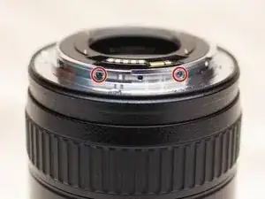
Remove the two 3mm JIS #00 screws on the side of the lens mount.
-
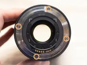
Remove the four 8mm JIS #00 screws holding in the metal lens mount.
-
-
-
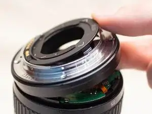
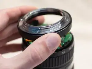
Gently lift up the side opposite of the contact assembly.
-
Slide your finger (or plastic spudger tool) under the lens mount and pop off the back plastic cover off of the lens.
-
Pull the lens mount assembly up and away from the lens.
-
-
-
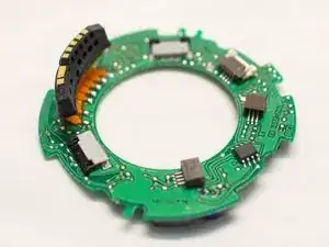
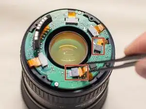
Use a pair of blunt tweezers to remove the two small ribbon cables from the main PCB board.
-
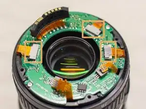
Disconnect the remaining three ribbon cables.
-
Use a pair of tweezers to gently pull back the locking tabs on the ribbon cable connectors.
-
Gently remove the ribbon cables.
-
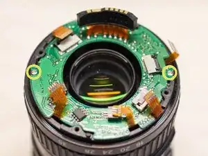
Remove the two 2.5mm JIS #00 screws from the main PCB board.
-
To reassemble your device, follow these instructions in reverse order. Use care when reconnecting the ribbon cable and ensure that they are properly seated in their connectors.