Introduction
-
-
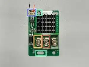
The used mounting holes are boxed in green
-
The red cable from the bed goes the Vout terminal boxed in red on the picture.
-
The black cable from the bed is moved from the -V screw terminal of the Power supply unit(PSU) to the +V screw terminal on the PSU
-
The red cable used to connect between the PSU +V and the SSR will now go to the screw terminal boxed in orange
-
New black cable will connect between the -V on the PSU and the V- on the MOSFET box in Black.
-
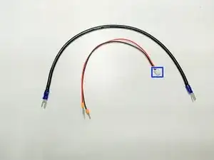
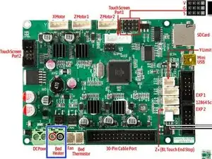
New jst pigtail connector cable will connect to the connector on the MOSFET boxed in blue and to the Control Board Bed positive and negative screw terminal for the bed heater
-
To reassemble your device, follow these instructions in reverse order.

2 comments
Hi AJ, thx a lot for your help! Klaus from TOP CLASSIC CARS LLC
Hi!
With a delay of 3 years... Thanks for the instructions! Would this be valid for the Creality CR 10s PRO v2? I got this model in 2019... it remained stuck on my mind that it was advertised back then as a v2, that's why i wrote it like that. But now I'm not sure as I found this component as a standard in cr10s pro v2 and mine had a SSR module for the heated bed. Well... the SSR module has reached it's time I guess and broke. I compared the mainboards ( mine vs the one in the picture) and I'm a bit confused as I cannot distinguish the marks on the big black square chip and also I have no idea if it matters anyway.
I hope someone can help me, as I don't want to give up on this printer.
Thanks!
Dragos
Dragos -