Introduction
-
-
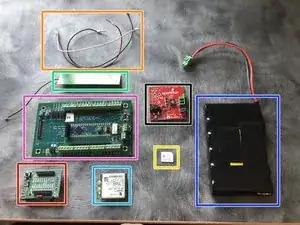
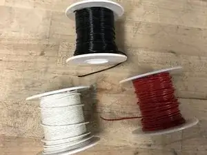
Red, black, and white wires
-
Battery with Pluggable Block
-
Activated SIM card
-
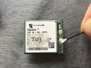
Pretested modem
-
Little pretested board
-
Big preprogrammed board
-
Cell antenna
-
Sunny buddy
-
-
-
Check any connection made using wires or screwed in pins by lightly tugging at them near the terminal
-
-
-
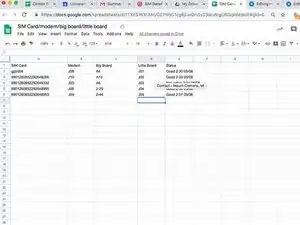
Create a google sheet in the team drive and record the corresponding parts as seen in the photo
-
-
-
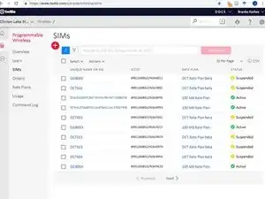
Make sure SIM cards have been activated by checking their status on Twilio while attached to a board and modem known to be working.
-
Here's a link to where you can check a SIM cards connectivity in Twilio: https://www.twilio.com/console/wireless/... The page should look like the first photo
-
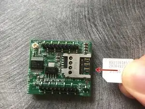
Type in the first two rows of numbers on the SIM card in the search bar to find it
-
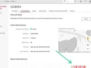
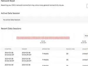
Once at the page for your specific SIM card click on connectivity and check to see if any red shows up on the timeline. An example of this can be seen in the second photo.
-
It takes a while for the connection to register on Twilio so wait a while and keep refreshing before determining the SIM card is not active.
-
Make sure the modem has been tested
-
Make sure the little board has been tested
-
Make sure the big board has been programmed
-
-
-
Obtain red, black, and white wires from spools seen in the first photo
-
Cut a length of six inches of each color
-
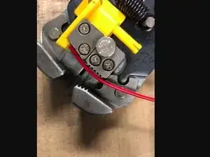
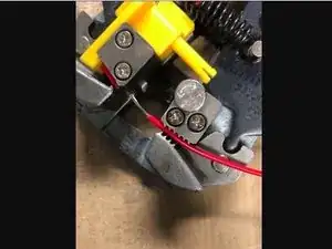
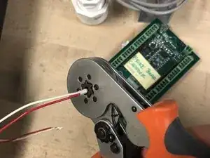
Strip the wires by placing them in the wire stripper and pressing together as seen in the second and third photos
-
-
-
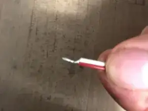
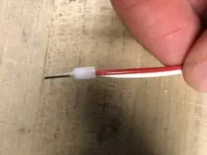
Twist one end of the red and white connectors together as seen in the first photo
-
Insert the wires into the head as seen in the second photo. Make sure they are inserted as far as possible
-
Crimp the metal end of the head by placing it in the crimper and pressing all the way down as seen in the third photo
-
Insert all remaining wire ends into heads and crimp the heads as previously described
-
-
-
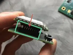
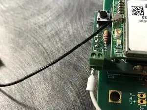
Align and insert modem pins into the small board pushing them all the way in as seen in the first photo. Make sure the ports of the modem are on the same side as the button of the little board.
-
-
-
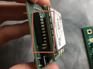
Simply insert the pins of the little board into the big board if it is configured as in the first photo
-
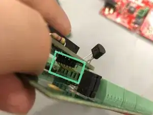
If the big board is configured as in the second photo, bend the pins of the little board and insert them into the terminals and screw them in
-
-
-
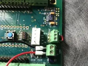
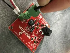
Screw in red and black connectors into big board terminal as seen be in the first photo
-
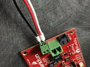
Screw in black connector and combined red and white connectors into sunny buddy terminal as scene in the second photo
-
Screw in white connector into little board terminal as seen in the third photo
-
-
-
Insert the battery as seen in the first photo
-
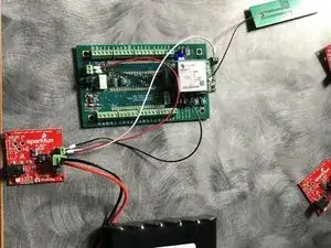
The final configuration can be seen in the second photo
-
-
-
Log into the same Twilio page as before and periodically monitor the connectivity
-
The connectivity should display a similar pattern to the first photo, and the packets downloaded and uploaded should be nonzero
-
Record the status of the connectivity in the google sheet you created in Step 4
-
To reassemble your device, follow these instructions in reverse order.