Introduction
Behringer Powerplay P16-HQ is a revision to the P16 that swaps several potentiometers for rotary encoders and LED position indicators (except there in no position indicator for the parametric EQ frequency setting), as well as a different DAC chip and headphone amp.
Disassembly is fairly straightforward. The QC on these vary and I needed to fix an incorrectly mounted side cover on one unit so I thought I'd take some pictures along the way. Enjoy.
-
-
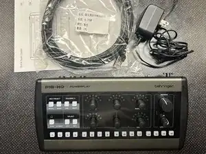
P16-HQ
-
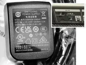
Switching Power Supply 12VDC 0.4A Output, Center positive.
-
Note: DC IN on the P16-HQ is labeled 12V 300mA
-
Ethernet Cable (Shielded SFTP, 4.75m, about 15 feet)
-
Quick Start Guide
-
-
-
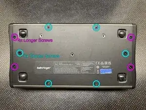
On the bottom of the P16-HQ, use a #2 Philips Screwdriver to remove all ten screws
-
The four longer screws go on the left and right edges
-
The shorter screws go on the top and bottom edge and the mid-plane which hold the internal PCB so they must be removed before you try to remove the bottom plate
-
If the plate is still firm use a spudger to pry it off - the top edge was the easiest for me.
-
Note: There are three additional screw holes for a mounting plate but they're not used otherwise
-
-
-
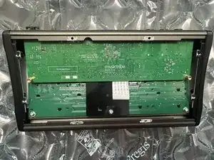
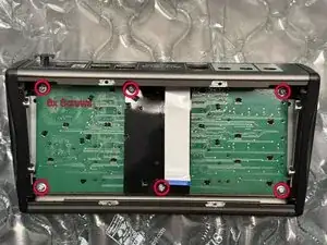
The IO/Processing board is labeled MusicTribe 0609-AAB, PCB331032REVM_02
-
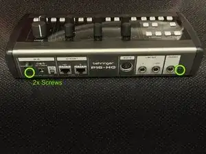
Caution! The IO/Processing PCB is held in by two screws on the rear, when you remove them the PCB will be loose but connected by a ribbon cable
-
Remove the two screws on the rear of the P16-HQ housing
-
Carefully lift the IO/Processing PCB from the case
-
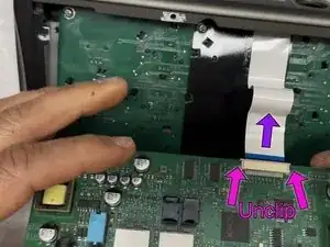
Flip the PCB over toward the front edge of the P16-HQ, unclip the ribbon cable and remove it
-
Finish removing the now disconnected PCB from the case
-
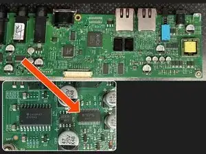
Click Image #3 for a zoomed in glam shot of the board which includes chips labeled: XMOS V16A0 (Could be a XU316), A couple Cirrus Logic 8416-CZZ, an GigaDevice GD32F303 and MIDAS M9000 DAC, and a TI TPA6120A2 headphone amp.
-
-
-
Important: Before unscrewing the button and control board you must carefully remove all the plastic knobs from the top control surface. I used a pinching motion to pull the knobs away without bending them side to side. If they are very tight try warming them up a bit, gentle heat, like 105F
-
After removing all the knobs, unscrew the six silver screws
-
Carefully remove the buttons & controls board. If it's stuck you can push on the knob stems and buttons from the top
-
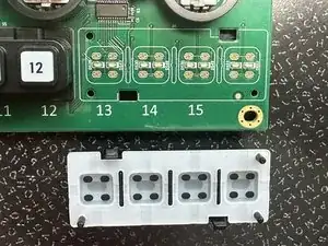
On the bottom of the PCB there are lots of black clips that correspond to the button housings and LED housings on the top of the board. Unclip to remove only if you need to
-
-
-
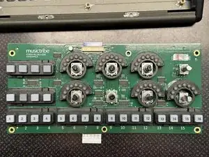
The Buttons & Controls board is labeled MusicTribe C003-01243-000, PCB403012REV01_01
-
You can remove the buttons and LED shrouds by unclipping the housings from the back of the board, being careful not to break them. I found using a spudger helpful. I wouldn't remove them if you don't need to since membranes switches are sensitive to contamination
-
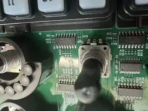
There's not much on the board except lots of 74 series shift registers (74HC165D) and MacroBlock MBI5020 LED drivers. The rotary encoders appear to be six identical Dongguan LJV branded ones although not sure on the specific model.
-
-
-
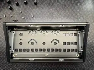
The case consists of:
-
Metal Housing
-
Two Plastic Endcaps mounted to metal brackets
-
Faceplate (Transparent w/Printed Graphic attached with adhesive)
-
There are four screws concealed by the faceplate, two for each of the endcaps. If you need to adjust the endocaps without fouling the faceplate adhesive, it is possible to turn the screws from the threaded end with pliers- the will likely destroy the threads so you can choose your method carefully.
-
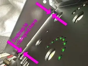
The endcaps are each secured by two mounting screws, two clips that are pinched by the case and the metal bracket and two longer back plate screws that also pinch against the metal bracket.
-
The second picture shows the gap under the metal bracket after an endcap is removed.
-
It is possible, and perhaps even easy, to pull the faceplate up, but I only lifted a small corner with a spudger.
-

To reassemble your device, follow these instructions in reverse order.