Introduction

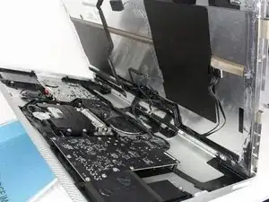
After the LCD is removed, it looks like the webcam and microphone are right within reach. The two wires that are connecting them to the main logic board are behind a lot of the other wires and components making it a little tricky to get to their connectors and take them out. Also, since the microphone is held in by adhesives, a prying tool is absolutely essential to replace it!

  1. vKYkNXJG6EyYZXwb
    vKYkNXJG6EyYZXwb
    bdoSe25Kx2AEFnuf
    Fy6tFKoYcjhdx4uu
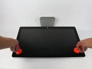
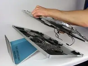
    • Lay down the display with screen side up.

    • Since the display is able to be tilted up and down, we found it useful to prop up the screen up with a styrofoam block in between the screen and the base.

    • Place the two suction cups on both sides of the top of the screen and make sure to lock them in place.

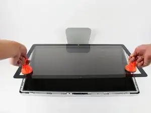
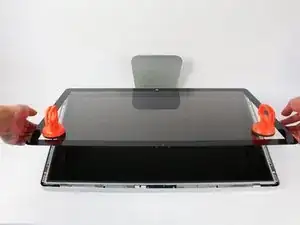
    • The glass screen is connected to the rest of the display by small magnets. Lift slowly and the screen will come right off.

    Instead of $14 foam block, I used a full roll of paper towel and two pillows. While it worked, if I ever did this again, I would buy the block of foam. Since you’re removing a power cable, you need to be able thread it through and I think the foam block would make that easier.

    Josh Miller -

    You can also use a single handle, double cup floor lifting suction cup. Just place it in the centre of the screen near the camera and lift slowly.

    Steve A -

    I just used a toilet plunger to remove the screen and it worked like a charm!

    Philip Jacob -

    That’s what I call resourceful—made my day. I hope your repair was successful.

    Tobias Isakeit -

    Great idea, thanks a lot!

    Yvan Sandoz -

    The glass lifted off the magnets quite easily after just using my fingernails. No suction cups or toilet accessories needed.

    Adrian Gropper -

    I had the same problem and after removal of the fan and a bit of work with the vacuum, the fan is quiet. Thanks to ifixit for the great instructions that made this easy.

    John Perser -

    To keep the screen up, other soft objects might work, but it's important that the hole in the back isn't covered because you will need to thread the new Thunderbolt/MagSafe cable through it and it would be a hassle to do it after everything's been set up.

    Thomas -

    Anybody got any links to glass screen replacement supplier for the A1407 Thunderbolt Display? Im finding it impossible to find a replacement without it being crazy money.

    Michael McMillan -

    Instead of a wedge, I used 4 rolls of toiletpaper, one under each corner.

    jnbruin -

    Glass screen cover came out just using my fingernails. Used a tupperware container as a prop to keep the screen at a good angle to access the cords underneath.

    MeepleMe -

  2. y1QM4GJuH1vKrEUg
    y1QM4GJuH1vKrEUg
    xV1xJRpqEugIUYOL
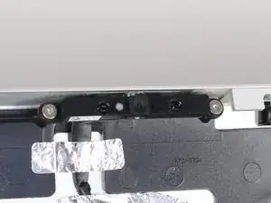
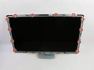
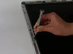
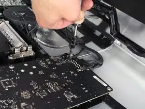
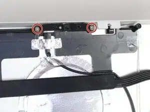
    • Unscrew the 12 screws around the side edges and the top of the LCD with the TR 10 Screwdriver.

    The screws marked in orange don't need to be removed, all they do is hold the magnets on the LCD.

    Garrett Mace -

    Yes “orange screws” does not need to be removed.

    You do not need a TR10 screwdriver as written in the text a T10 will suffice (more common and also correctly mentioned in the list of tools).

    A TR10 screwdriver is compatible with the T10, but not the other way around

    Per Lohmann Poulsen -

    On mine, the orange screws did hold the LCD down; the magnets were held in by TR6 screws, and those did not need to be removed.

    jml9904 -

    Any info on if an older 2011 imac screen could just be plugged into this to replace the current lcd?

    Nathan Morris -

  3. dNtDx1LZQDU1OVbo
    dNtDx1LZQDU1OVbo
    OSaiV2IVJO3u5HPx
    • Slowly lift the LCD out from its placement and tilt it upwards.

    • It can be very helpful to have an extra set of hands to hold the LCD up while you work with the cables underneath.

    • There are four wires that connect the LCD to the rest of the components. Make sure not to pull hard and break any of the wires.

    Add the note that it should be lifted from the bottom edge. It is also important not to twist the display by levering up from one corner.

    Charlie Nancarrow -

    Before lifting the monitor, you should be prepared to start collecting screws and have your TR 10 ready.

    Josh Miller -

    Having a couple of short screwdrivers handy to prop up the LCD (like you would a car hood) while you disconnect the cables helps.

    jml9904 -

    I’m against the screwdrivers. You can buy a computer repair toolkit

    deltonis -

  4. vYMImIhPgImDC4sZ
    vYMImIhPgImDC4sZ
    KwPHhIYJrH6vl4ZA
    ltsqwLZEIXOkvKZf
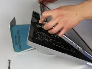
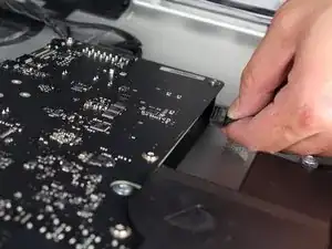
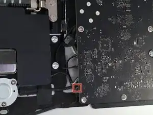
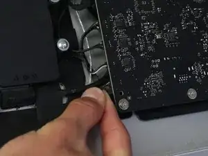
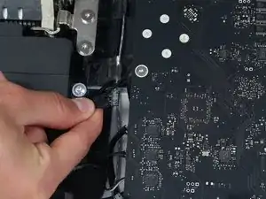
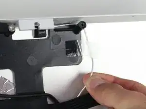
    • For the first of the four wires (furthest away from the wire that is held in by a screw), grab onto the connector and pull slowly.

    Note: be sure to pull away but not hard. Wiggle and pull slowly. These are delicate especially due to age.

    Overall this is a moderate repair. Follow step by step and you are good.

    Also, use tape and/or labels to mark which cables go where per the MLB and other parts. Resulting in easier reassembly.

    Ted Teske -

    Connector wires face upwards on this piece.

    MeepleMe -

  5. aJXhUDyuRDBEYIPX
    aJXhUDyuRDBEYIPX
    TvkYkf3pUBHBJZEQ
    N6oVUvAxqymMUFXn
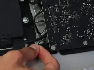
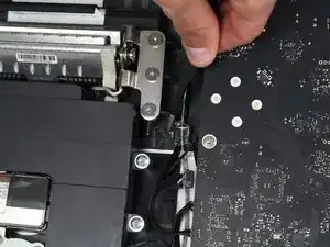
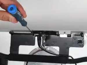
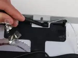
    • For the next connector, which is right next to the previous wire, there is a piece of tape attached to a metal bar.

    • Flip the metal bar over using the tape as a handle.

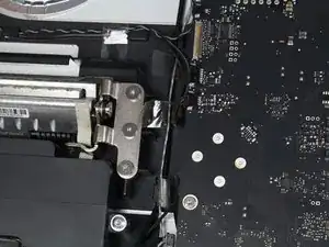
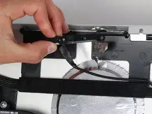
    • Next, grab onto the connector and slowly pull it from the socket in the logic board.

    What is this connector for?

    pdspanagel -

    I imagine this connector is going to be for display data (i.e. LCD data).

    Scott Havard -

    I pretty much mangled this cable trying to put it back into the slot. Is this something I can order a replacement for?

    Ryan Stryker -

    I also screwed up this wire.

    erybovic -

    I also screwed up this wire. Wondering what the wire name is.

    erybovic -

    Thunderbolt Display 27" LVDS Cable

    Klaus Finke -

    As other’s have said, this cable is super delicate.

    When you replace it, make sure that the small metal handle it firmly reattached to the other side of the port. I thought I’d got it right first time, but had no video signal (thunderbolt detected display, and power was fed to the Macbook Pro).

    I had to reinsert this one again, and one in, firmly press the connector home, then latch the handle over the other side. I also gave it a test pull to ensure it was secure. Then all was well!

    Steve A -

    Managed to remove it but broke one pin putting it back. I don’t understand why they make so fragile with all the space available…

    BAULARD -

    Can anyone provide a photo of this connector so as to give a better understanding of its mechanics? see this cringe worthy effort at guidance; https://youtu.be/A96CUSm_Xhs?t=1050

    Philip Sharp -

    No mention of static electricity precautions- is that not a concern with displays?

    baggins -

  6. yYhUxvsdBk3pv3Io
    yYhUxvsdBk3pv3Io
    EyjpfRYE2bE1xGWk
    a4reZswHC1EsBc11
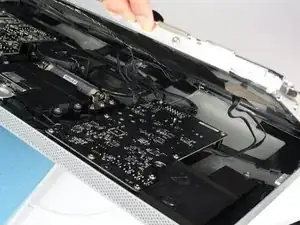
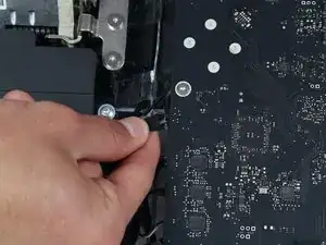
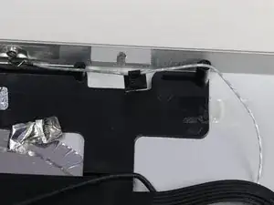
    • For the connector on the other side of the logic board, grab the connector from underneath and carefully pull it from the board.

    To remove this connector, you squeeze the lower tab to unclasp it, and pull it sideways away from the board

    Brad Bell -

    This cable was also taped for me, so remove the tape first

    danmcfalls -

  7. sjOHkIKEoj3IwvE6
    • For the last wire connecting to the LCD, use your T 10 Screwdriver to remove the screw.

  8. fGJtJg1gy2EQTqVl
    fGJtJg1gy2EQTqVl
    XNFyMYy5JtA3VvQX
    • The LCD has now been fully disconnected from the casing and can be repaired/replaced!

    • its best to set the LCD on a bed or on a thick towel to avoid damage to the LCD

    Can this be replaced with an LCD from an imac?

    Nathan Morris -

  9. 1VZLTCGYOoQ21IJ6
    1VZLTCGYOoQ21IJ6
    JneqgH4XrEKnCZUx
    pKfJI6VgYMZOmyQd
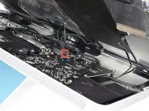
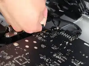
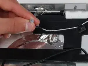
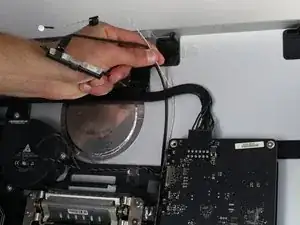
    • The webcam and microphone are located at the top of the device. First, follow the white microphone wire down to its connector in the logic board.

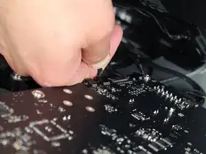
    • Carefully pull the white wire's connector from the logic board.

  10. VUlfKubFDKFYpoKb
    VUlfKubFDKFYpoKb
    yGM3nyondKgVSyH1
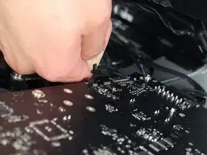
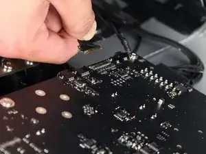
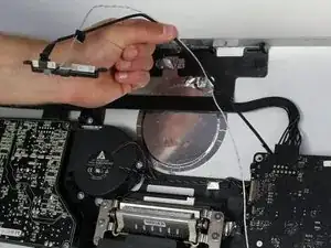
    • Follow the wire down from the webcam and find where it is connected into the logic board.

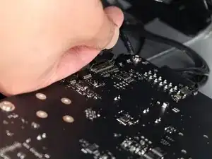
    • Carefully remove the connector from the logic board.

  11. JuEMwXxkjlC4Tw5V
    JuEMwXxkjlC4Tw5V
    MjOHALsE6ws4MrIH
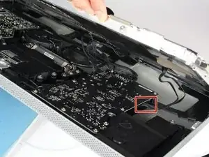
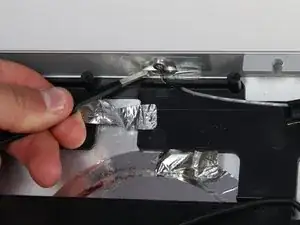
    • The wires are held in place by three pieces of tape. Remove the tape out of the way so that the wires are free.

    • It is very easy to remove the pieces of tape using tweezers. They aren't completely necessary though.

  12. WmjQeMSHG2TOt511
    WmjQeMSHG2TOt511
    SSG15mmoldFDiMiF
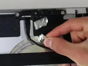
    • Back at the top of the device, there are two pieces of silver tape holding the webcam wires in place.

    • Again, tweezers are helpful but aren't necessary for removal of the silver tape.

    • Next, remove the tape that is holding the microphone in place.

  13. KNgeN65ykZILswHB
    KNgeN65ykZILswHB
    lmc6lMmJ2dMVbxgr
    F4StWPB3tACg6rYm
    • The webcam is held in with two screws and a connector

    • Unscrew the two screws holding the webcam in place with the TR 10 screwdriver.

    • The webcam is now free from your display!

  14. lnrBRMJrqt6pgF24
    lnrBRMJrqt6pgF24
    SJuPupFCx2X5ZCyN
    • With the webcam removed, the microphone is now visible.

    • The webcam is held in place with a plastic clip that has foam adhesive stuck to the casing.

    • Use a plastic spudger to pry underneath the clip and separate the clip from the casing.

    I have not done this repair yet, but from the images, think there’s a mistake in the instructions, and it should say, “The microphone is held in place with a plastic clip that has foam adhesive stuck to the casing.”

    Adam Scoville -

  15. m3yO4EswLwhcV2H4
    m3yO4EswLwhcV2H4
    YEtTP3MQB6BcE3Vm
    • The actual microphone itself is stuck to the top of the casing using a small amount of adhesive and covered by a piece of tape.

    • Remove the piece of tape using either tweezers or your fingers to have access to the microphone.

    • Use the plastic spudger again to get underneath the small round microphone and pry it loose from the adhesive.

  16. UIepSlqpdGaDIU4b
    UIepSlqpdGaDIU4b
    6ZDvmD2aXfTYlbAO
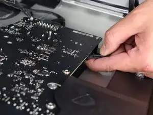
    • The wires for both the webcam and the microphone are tucked underneath a few other components.

    • Carefully pull the wires out up and out from the other components and your webcam and microphone can be replaced.

Conclusion

To reassemble your device, follow these instructions in reverse order.

Wesley Ho

Member since: 14/04/15

455 Reputation

0 comments