Introduction
This guide demonstrates how to replace the thumbsticks, also known as the joystick or analog stick, on the Anbernic RG353V. The thumbsticks allow the user to move in multiple directions within a game using the tilt of their thumb.
If your thumbsticks aren't registering or start to drift, you may want to replace them.
This guide requires some patience, as the thumbstick wires can be difficult to reattach. Before you begin this repair, make sure to turn off the device and unplug it from the charger.
-
-
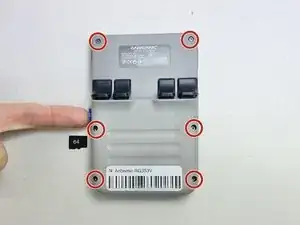
Use a 2 mm Hex screwdriver to remove the six 7 mm screws from the back case of the handheld game.
-
Use an opening tool to pry the top and bottom of the game apart. Work the tool around the perimeter of the device between the seam to release the snap tabs.
-
Separate the top and bottom cases gently.
-
-
-
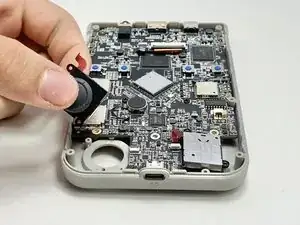
Push on alternating sides of the connector to disconnect the battery wire from the main circuit board.
-
If that doesn't work, use a pair of tweezers to firmly grip the sides of the connector and pull straight away from the socket. Hold the tweezers closer to the connector to get a better grip.
-
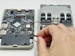
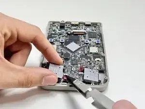
To disconnect the cable coaxial cable, slide a thin, ESD-safe pry tool or angled tweezers under the metal neck of the connector (as close to the head as possible) and lift straight up from the board.
-
-
-
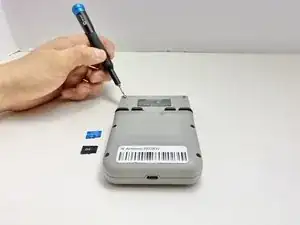
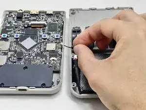
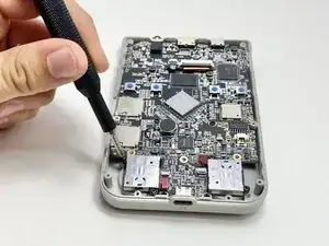
Use a Phillips #00 screwdriver to remove the five 7 mm Phillips from the plate covering the bottom of the circuit board.
-
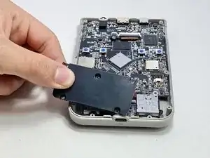
Remove the black cover.
-
-
-
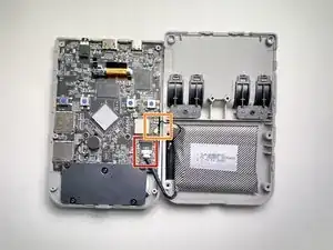
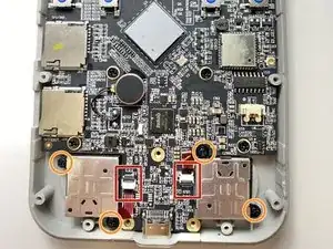
Use a spudger to flip up the locking flaps of the ZIF connectors.
-
Use tweezers or your fingers to gently pull the red ribbon cables out of their sockets.
-
Use a Phillips #00 to remove the four 6 mm screws attaching the thumbsticks to the circuit board.
-


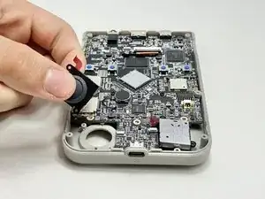
Follow these steps in reverse order to slot in the replacement thumbsticks.