Introduction
The screen is the component that produces light to display specific pixels, forming images for the user to interact with and interpret the device's activity.
You may need to replace the screen of your Anbernic RG353V if it's damaged, cracked, or faulty. If your screen is flickering or the light level isn't right, refer to this troubleshooting guide.
This guide demonstrates how to replace the screen of the Anbernic RG353V handheld console. It is the most challenging component to replace, requiring near-complete disassembly of the device.
Before you begin this repair, make sure to power off the device, and unplug it from the charger.
-
-
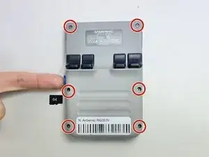
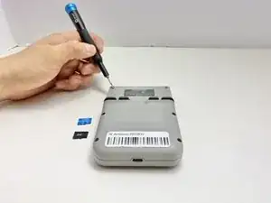
Use a 2 mm Hex screwdriver to remove the six 7 mm screws from the back case of the handheld game.
-
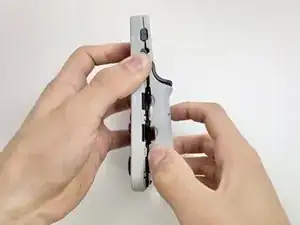
Use an opening tool to pry the top and bottom of the game apart. Work the tool around the perimeter of the device between the seam to release the snap tabs.
-
Separate the top and bottom cases gently.
-
-
-
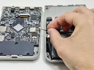
Push on alternating sides of the connector to disconnect the battery wire from the main circuit board.
-
If that doesn't work, use a pair of tweezers to firmly grip the sides of the connector and pull straight away from the socket. Hold the tweezers closer to the connector to get a better grip.
-
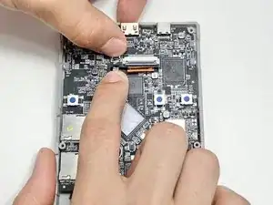
To disconnect the cable coaxial cable, slide a thin, ESD-safe pry tool or angled tweezers under the metal neck of the connector (as close to the head as possible) and lift straight up from the board.
-
-
-
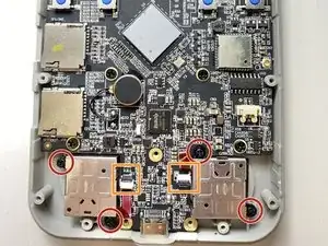
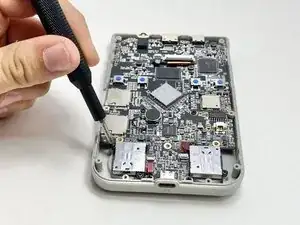
Use a Phillips #00 screwdriver to remove the five 7 mm Phillips from the plate covering the bottom of the circuit board.
-
Remove the black cover.
-
-
-
Use a Phillips #00 to remove the four 6 mm screws attaching the thumbsticks to the circuit board.
-
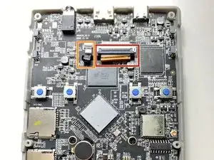
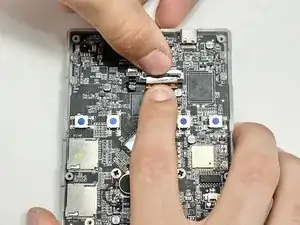
Use a spudger to flip up the locking flaps of the ZIF connectors.
-
Use tweezers or your fingers to gently pull the red ribbon cables out of their sockets.
-
-
-
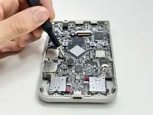
Use a spudger to flip up the locking flap of the ZIF connector.
-
Use tweezers or your fingers to gently pull the bronze-colored ribbon cable out of its socket.
-
Use a spudger to flip up the locking flap of the ZIF connector.
-
Use tweezers or your fingers to remove the small black ribbon cable from the socket.
-
-
-
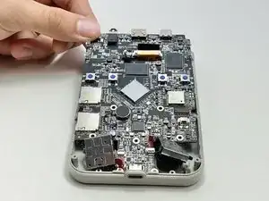
Use a Phillips #00 screwdriver to remove the four 5 mm screws that secure the circuit board to the case.
-
-
-
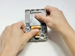
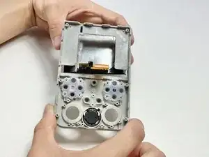
Remove the black tape at the top of the device.
-
Insert the iFixit opening tool in between the case frame and the metal screen plate to separate the adhesive from each side.
-


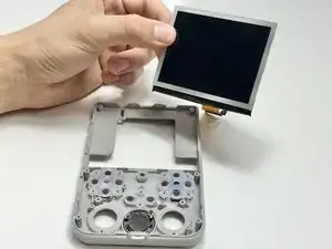
To reassemble your device, follow these instructions in reverse order. Apply new adhesive where necessary after cleaning the relevant areas with isopropyl alcohol (>90%). Take your e-waste to an R2 or e-Stewards certified recycler.