Introduction
The D-Pad button is located on the front left of the device, which means the user will need to remove the circuit board to get to it. This button is used primarily for selecting and moving the cursor or entity in the device software. This guide shows how to replace the Anbernic RG353V D-Pad button.
Before you begin this repair, make sure to power off the device, and unplug it from the charger.
-
-
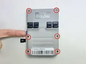
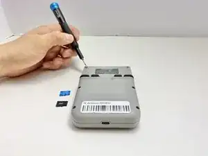
Use a 2 mm Hex screwdriver to remove the six 7 mm screws from the back case of the handheld game.
-
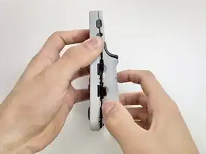
Use an opening tool to pry the top and bottom of the game apart. Work the tool around the perimeter of the device between the seam to release the snap tabs.
-
Separate the top and bottom cases gently.
-
-
-
Push on alternating sides of the connector to disconnect the battery wire from the main circuit board.
-
If that doesn't work, use a pair of tweezers to firmly grip the sides of the connector and pull straight away from the socket. Hold the tweezers closer to the connector to get a better grip.
-
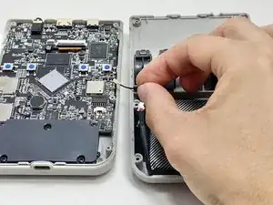
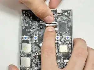
To disconnect the cable coaxial cable, slide a thin, ESD-safe pry tool or angled tweezers under the metal neck of the connector (as close to the head as possible) and lift straight up from the board.
-
-
-
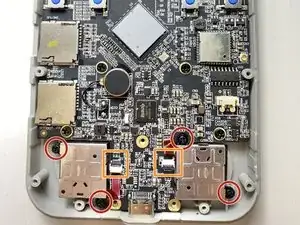
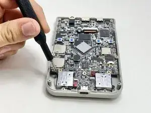
Use a Phillips #00 screwdriver to remove the five 7 mm Phillips from the plate covering the bottom of the circuit board.
-
Remove the black cover.
-
-
-
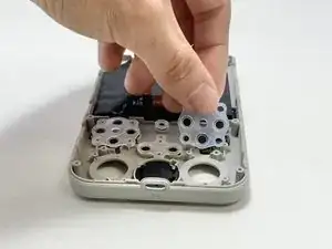
Use a Phillips #00 to remove the four 6 mm screws attaching the thumbsticks to the circuit board.
-
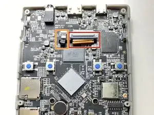
Use a spudger to flip up the locking flaps of the ZIF connectors.
-
Use tweezers or your fingers to gently pull the red ribbon cables out of their sockets.
-
-
-
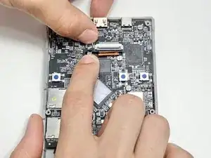
Use a spudger to flip up the locking flap of the ZIF connector.
-
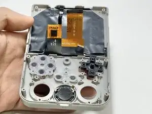
Use tweezers or your fingers to gently pull the bronze-colored ribbon cable out of its socket.
-
Use a spudger to flip up the locking flap of the ZIF connector.
-
Use tweezers or your fingers to remove the small black ribbon cable from the socket.
-
-
-
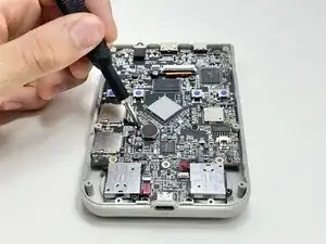
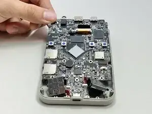
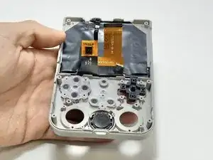
Use a Phillips #00 screwdriver to remove the four 5 mm screws that secure the circuit board to the case.
-


To reassemble your device, follow these instructions in reverse order.