Introduction

Use this replacement guide if the camera of the Amazon Echo Show 8 is not functioning. The camera is important when it comes to unlocking the device using facial recognition and video calling. Before continuing with this replacement guides, go to the troubleshooting guide and ensure you have completed the trouble shooting steps. This guide will walk you through replacing the camera. Make sure the device is disconnected from the power before proceeding with the guide.

  1. A42yxFCW6uxivLsY
    A42yxFCW6uxivLsY
    KRmCe1bblmcDgUWF
    hvs2ngiPZM4kt3te
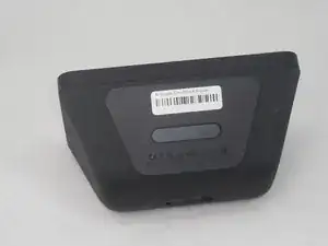
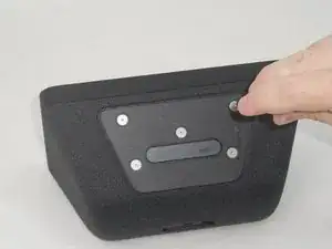
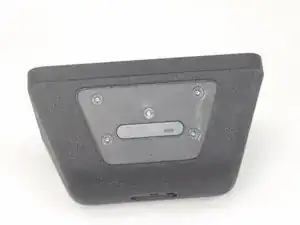
    • Flip the device so that the rubber foot is facing up.

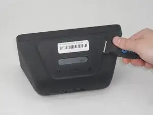
    • Insert a Jimmy between the rubber foot and chassis, then slide it around the perimeter until the rubber foot releases.

    • The adhesive that holds the rubber mat on may require some force to sever.

    • Remove the rubber foot.

  2. 1NZcPJovanrBsxJe
    1NZcPJovanrBsxJe
    XfOSddypHvhEnaxT
    QgNNaGaplikWD3bF
    • Use a T6 Torx screwdriver to remove the five 4.5 mm screws from the base of the device.

  3. WNGnZE3i6boSViMF
    WNGnZE3i6boSViMF
    JfFxUiJDEG3QEwjo
    5jlgwtRryFgA41PF
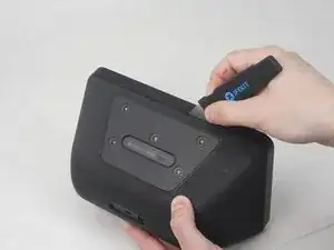
    • Insert a Jimmy in the gap between the front and rear case.

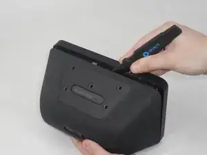
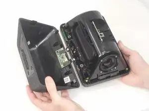
    • Work the Jimmy around the perimeter to gently detach the rear case from the front case.

    • Separate the rear case from the front case.

    • There are 2 thin ribbon cables connecting the microphone board to the back cover. Take care not to tear or strain them as you separate the cases.

  4. MyoNisvZHigXJjxX
    MyoNisvZHigXJjxX
    a1shI2TVGhyXQpQ5
    PgQXEYAGBTGAWXTd
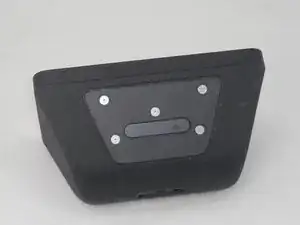
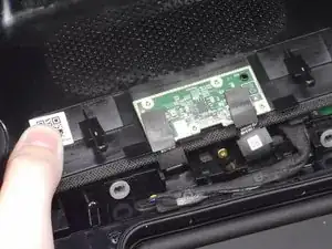
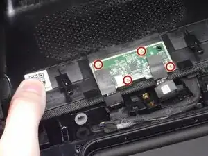
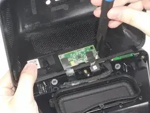
    • Use a T6 Torx screwdriver to remove the four 5.2 mm screws that secure the microphone board to the rear case.

  5. VQtbSfWnrDklGUEX
    VQtbSfWnrDklGUEX
    SgaNQQMSeSxRn4il
    3eAKl3HSfHiv6JLj
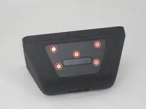
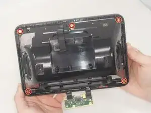
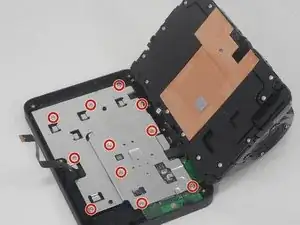
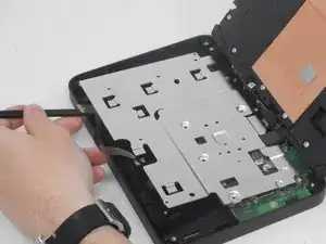
    • Use a T6 Torx screwdriver to remove the six 7.6 mm screws that secure the speaker housing to the screen assembly.

    • There is a screw that is not pictured in the center of the bottom two screws.

  6. gxufEiE11VsD2jZJ
    gxufEiE11VsD2jZJ
    sowvJrtYqJpLeAmT
    GD5kygoRiPJcqUGQ
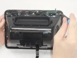
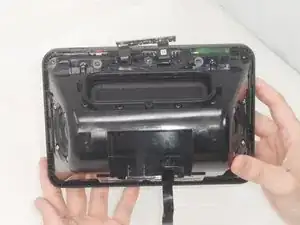
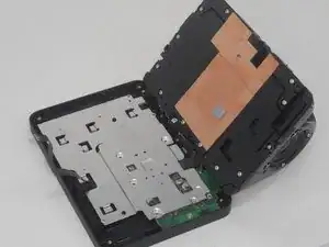
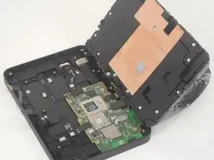
    • Gently separate the speaker housing from the display assembly and set the device on a flat surface.

    • There is a cable connecting the speaker housing to the display assembly. Take care not to pull on it while separating the two parts.

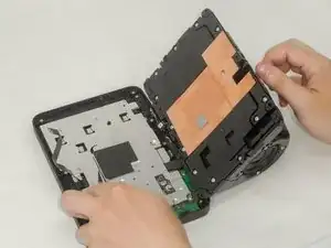
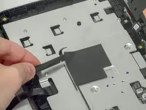
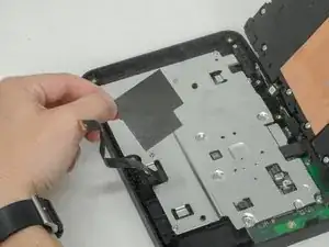
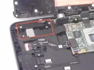
    • Use a plastic spudger to pry up and remove the foam mat at the center of the silver bracket.

  7. Sab2P3KLQU6NfMD1
    Sab2P3KLQU6NfMD1
    TKxAcGgyIATWfouX
    • Use a T6 Torx screwdriver to remove the eleven 6 mm screws that secure the silver bracket.

  8. RCcogZQUuRJJvIWu
    RCcogZQUuRJJvIWu
    SIPjqZICVSZ1OywC
    UYGO5YiCBauIRNnO
    • Use a plastic spudger to lift up the remove the silver bracket.

    • The camera is located to the left of the mother board.

  9. f1O61OLLISThAJqM
    f1O61OLLISThAJqM
    cWaVaCR6SjPTSDaj
    4TehCKdGxUQsEnIu
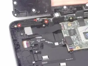
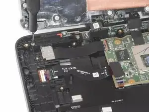
    • Use a T6 Torx screwdriver to remove the two 6 mm screws that secure the camera retention plate.

  10. Aoktkq4X3IghuTsx
    Aoktkq4X3IghuTsx
    SP4pJIqPjETO1HnB
    nLZJLQFHjoPuRSOv
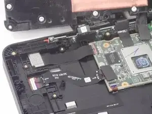
    • Use a spudger to slightly lift the camera retention plate.

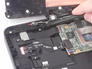
    • Lift the camera retention plate up and out of the chassis.

  11. CElQFyVlMcfFcvyv
    CElQFyVlMcfFcvyv
    vr2ujp3rYakqdF4n
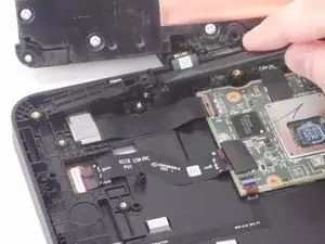
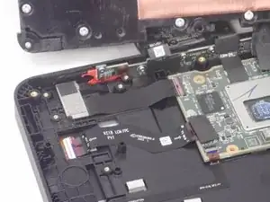
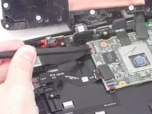
    • Use the pointed end of a spudger to flip up the camera ribbon cable ZIF locking flap.

    • Pull the ribbon cable directly out of its socket.

  12. gLLHrv2RIGUjZIdL
    gLLHrv2RIGUjZIdL
    DChLYQChhkSGZcmd
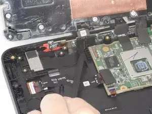
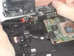
    • Lift up the camera gently, and use the pointed end of the spudger to gently remove the thin black ribbon cable.

    • The thin tab holding is held down with adhesive. Be gentle when removing it to prevent tearing it.

Conclusion

To reassemble your device, follow these instructions in reverse order.

Brian Le

Member since: 14/02/24

678 Reputation

0 comments