Introduction
This is a step-by-step guide to removing the buttons from an Amazon Echo Show 2nd Gen. For the purpose of cleaning the buttons, and removing any debris. This process can be done in just a few simple steps with the help of a screw driver!
-
-
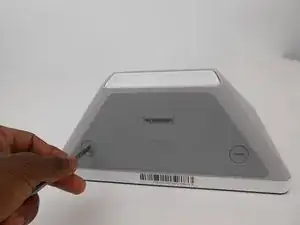
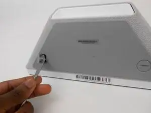
Turn the two screw plugs counterclockwise with a metal spudger until they are 90 degrees from their original position.
-
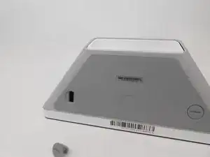
Pull each of the plugs out.
-
-
-
Use the metal spudger to pry and create space between the sound foam and the frame.
-
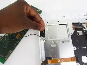
Once you have sufficiently pried the foam from the frame on each side, detach the sound foam from the frame with your hands.
-
-
-
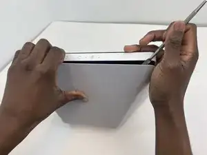
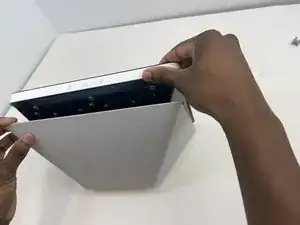
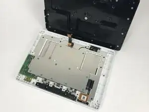
Firmly grasp the white trim of the front piece with one hand while the other pulls back on the black back portion of the device.
-
-
-
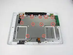
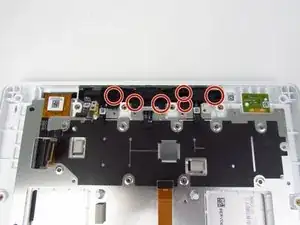
Remove all of the red 2 mm screws using a T5 torx screwdriver.
-
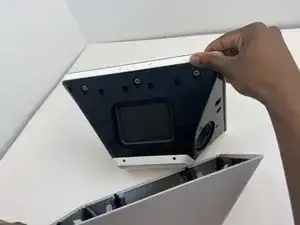
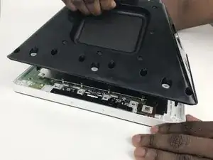
Carefully lift away the metal plate.
-
-
-
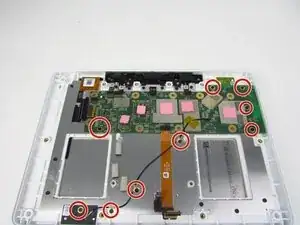
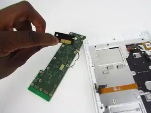
Using a T5 torx screwdriver, remove all 2 mm screws from the motherboard.
-
Remove all orange marked screws from the second metal plate.
-
-
-
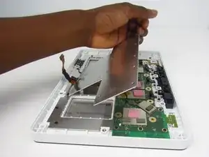
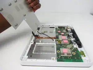
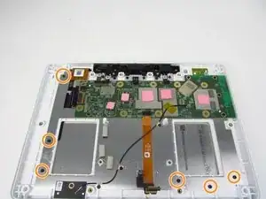
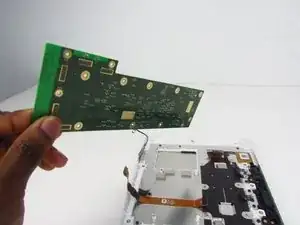
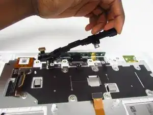
Remove the motherboard from the device. Be sure to be careful when removing the black adhesive.
-
-
-
Remove all 2 mm screws that are attached to the black plastic button casing.
-
Remove the case that holds the buttons. Buttons should now be free to remove.
-
To reassemble your device, follow these instructions in reverse order.

One comment
These instructions are missing one important step, at least on my version of the Echo Show 10 2nd gen. There are 8 Tr8 screws holding the big black backside with the speakers + sound card in place 4 at the top, 2 on each side and 2 at the bottom.
These 8 screws need to be removed before separating the back from the front in Step 3 of this guide.
To get to the 2 screws at the bottom the white cover which covers the sound-card and the connectors on the back needs to be removed as is described in the Sound Card replacement guide. Note the white cover is not only attached with 6 tr1 screws there also is some double-sided tape holding it in place at the edge near the power-connector you can see the tape remains at the first Picture of step 3 of the Sound Card replacement guide.
Since the white cover needs to be removed anyways it is easier to remove the cables to the sound card on the sound card side, as is shown in step 5 of the Sound Card replacement guide.
Since you didn’t use prerequisites, my comments on these steps have not transferred. Please be sure to see where I gave feedback and apply here.
Alex Watkins -