
Introduction
This guide will walk you through the replacement process for the motorized swiveling component found within your Amazon Echo Show 10 3rd Gen device. The motor is responsible for allowing your Amazon Echo device to swivel and track movement when enabled. If you are having issues with the device being unable to turn and track either automatically or manually, there may be an issue with the motor component of the device and it may need replacement.
Please ensure that the camera is turned on and rotation is enabled before deeming the component in need of replacement. Please see the Amazon Echo Show 10 3rd Gen troubleshooting page for more details.
This guide requires you to pry and remove multiple components that have been glued on.
-
-
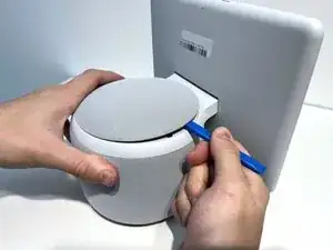
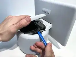
With the echo device standing upright, firmly grip the base and use the blue opening tool to gently pry the lid from the mesh speaker base.
-
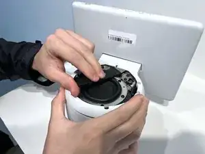
Remove the lid and set it aside.
-
-
-
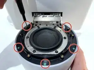
Use a TR8 Torx Security screwdriver to remove the six 9 mm screws from the perimeter of the plastic bezel on the top edge of the device.
-
-
-
Release the adhesive seal connecting the bezel to the main base by inserting a Jimmy underneath the edge, and gently sliding from one side to another.
-
Lift up the outermost edge of the plastic bezel (furthest from the display) to remove it and set it aside.
-
-
-
Use a Torx T6 screwdriver to remove the five 10 mm screws from the perimeter of the top surface of the base.
-
-
-
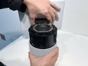
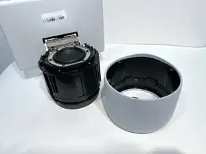
With one hand securely holding the neck of the display and the other holding the device base, gently lift the device out of the mesh shell.
-
Place the shell aside.
-
-
-
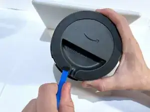
Turn the device on its side with the bottom facing upwards and out.
-
Use a blue opening tool along the edge of the base to pry off the adhesive strip.
-
Gently pull off the strip and place it aside.
-
-
-
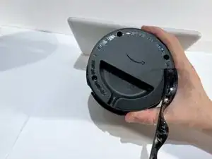
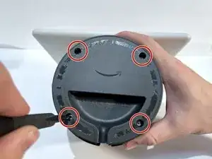
Use a T10 Torx screwdriver to remove the four 9 mm screws from the perimeter of the bottom surface of the device.
-
Remove the plastic base cover and set it aside.
-
-
-
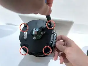
Use a Torx T10 screwdriver to remove the four 11 mm screws from the motor mount on the protruding ledge on the bottom of the device.
-
-
-
Tilt the device so the side of the base beneath the connection to the display is facing upwards and in clear view.
-
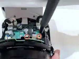
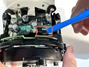
Use a T6 Torx screwdriver to remove the two 7 mm screws from the bracket covering the ribbon cable attached to the motor mount.
-
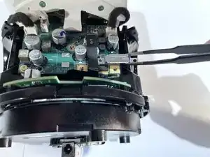
Use blunt nose tweezers to carefully remove the ribbon cable bracket and set it aside.
-
-
-
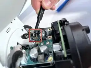
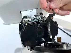
Place the tip of your opening tool under the edge of the press connector, and pry the connector straight up from its socket.
-
-
-
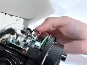
Use blunt nose tweezers to lift up the back of the connector to disconnect the ribbon from the socket.
-
Use tweezers or your fingers to gently grip the ribbon cable and pull away from the board.
-
Make sure the cable is only being held in place by its connection to the motor and the silver bracket on the underside of the base.
-
-
-
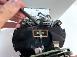
Use a T6 Torx screwdriver to remove the two 7 mm screws from the silver cable bracket on the motor mount.
-
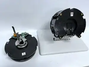
Remove the bracket, pull away the ribbon cable, and remove the motor.
-


To reassemble your device, follow these instructions in reverse order.