Introduction
-
-
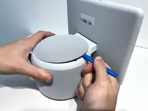
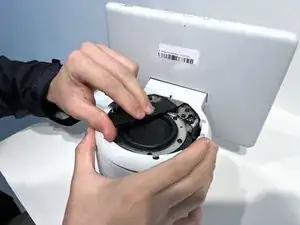
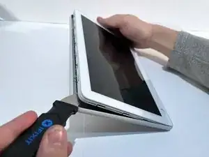
With the Echo device standing upright, firmly grip the base and use the blue opening tool to gently pry the lid from the mesh speaker base.
-
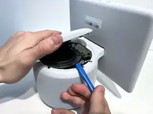
Remove the lid and set aside.
-
-
-
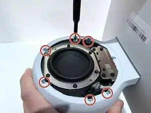
Use a TR8 Torx Security screwdriver to remove the six 9 mm screws from the perimeter of the plastic bezel on the top edge of the device.
-
-
-
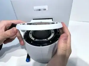
Release the adhesive seal connecting the bezel to the main base by inserting a Jimmy underneath the edge, and gently sliding from one side to another.
-
Lift up the outermost edge of the plastic bezel (furthest from the display) to remove it and set it aside.
-
-
-
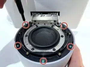
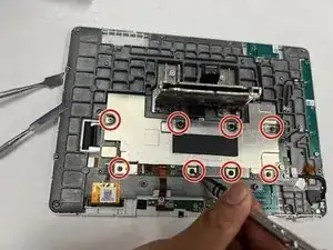
Use a Torx T6 screwdriver to remove the five 10 mm screws from the perimeter of the top surface of the base.
-
-
-
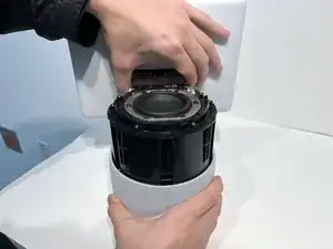
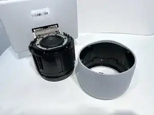
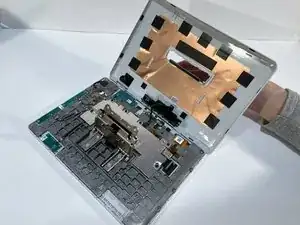
With one hand securely holding the neck of the display and the other holding the device base, gently lift the device out of the mesh shell.
-
Place the shell aside.
-
-
-
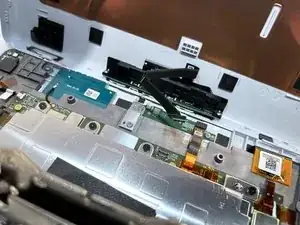
Tilt the device so that the underside of the display and its neck are facing you.
-
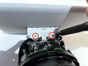
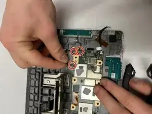
Use a T6 Torx screwdriver to remove the two 5mm screws from the underside of the display neck.
-
-
-
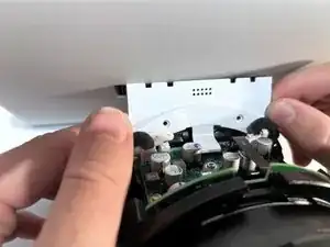
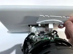
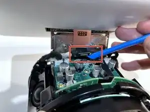
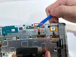
Use an opening tool to flip up the small locking flap on the ribbon cable connector located in the center of the exposed underside of the display neck.
-
Gently pull the cable out.
-
-
-
Tilt the device so it is in the upright position.
-
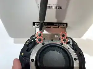
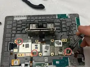
Use a TR10 Torx Security screwdriver to remove the four 11 mm screws from the top of the display neck.
-
-
-
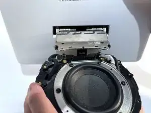
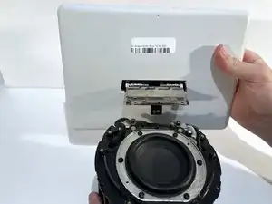
Insert a Jimmy along the seam of the screen and the shell and slide it along the length to separate the two sides.
-
-
-
Hold the display away from the board at an angle to ensure a clear view while keeping the ribbon cable slack.
-
Place the tip of your opening tool under the edge of the display connector, and pry the connector straight up from its socket.
-
Set aside the display.
-
-
-
Place the tip of your opening tool under the edge of the orange connector, and pry it straight up from its socket.
-
-
-
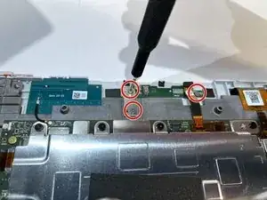
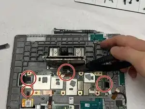
Use the T5 Torx screwdriver to remove the two 4 mm screws from the bracket covering the microphone board and the one 4 mm screw holding down the board itself.
-
-
-
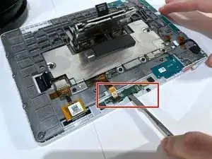
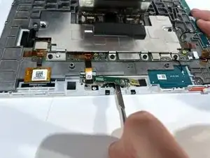
Use a spudger to pry under the microphone board. and gently wear away at the connecting glue.
-
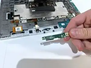
After the adhesive seal has been broken, gently lift and remove the microphone board.
-
-
-
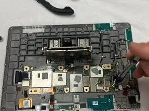
Use tweezers to remove the orange tape from the top of each ribbon cable.
-
Use tweezers to delicately pull each ribbon cable directly out of its socket.
-
-
-
Use the tip of a spudger to pry up and disconnect the three black antenna cables that connect to the display PCB.
-

To reassemble your device, follow these instructions in reverse order.