Introduction

If you're experiencing issues with your Amazon Echo Show 10 3rd Gen camera, such as poor image quality, malfunctioning during video calls, or a completely unresponsive camera, this guide will help you replace it and restore functionality.

Before starting, make sure to follow the Microphone Replacement Guide to gain access to the camera, as it is necessary to remove some internal components first.

By following this guide, you can resolve camera-related problems and get your Echo Show back to full working condition.

  1. Bf14dSULCCpgwAiE
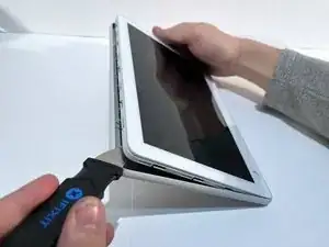
    • Insert a Jimmy along the seam of the screen and the shell and slide it along the length to separate the two sides.

    • For this particular step, a careful amount of force may be needed to separate the two parts. The connection is especially tight at the four corners. Use the iOpener to loosen the small amount of adhesive.

  2. MsgvSDjC1kDVx2YN
    • Gently separate the display from the base.

    • There is a small amount of glue holding the two components together in the top corner, which may require the user to apply more force when separating.

    • Don't yank the display off as it is connected by a cable.

  3. WoQ1QXSbFkpXwBHc
    WoQ1QXSbFkpXwBHc
    ISPrqEHHQ4ZnxJPc
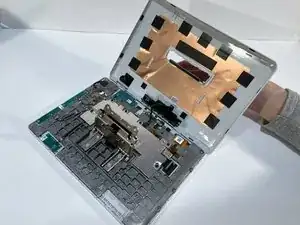
    • Hold the display away from the board at an angle to ensure a clear view while keeping the ribbon cable slack.

    • Place the tip of your opening tool under the edge of the display connector, and pry the connector straight up from its socket.

    • Be very careful to pry only under the edge of the connector, and not under the socket itself. If you pry under the socket, you will separate it from the circuit board, which requires specialized microsoldering skills and equipment to repair.

    • Set aside the display.

  4. A2aegkkLVjVwmBpH
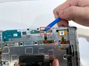
    • Place the tip of your opening tool under the edge of the orange connector, and pry it straight up from its socket.

    • To reconnect, align the connector carefully over its socket and press down with your fingertip—first at one side, then the other—until it clicks into place.

  5. N4TO1RNobpXrC2Pu
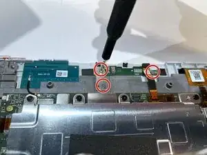
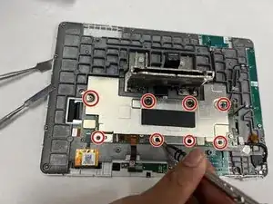
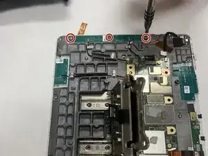
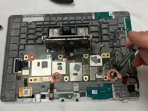
    • Use the T5 Torx screwdriver to remove the two 4 mm screws from the bracket covering the microphone board and the one 4 mm screw holding down the board itself.

  6. FuP2nZNfg25Eij4o
    FuP2nZNfg25Eij4o
    P5GemCRyL1JZFj6V
    5o13pGAMFDhoGYZW
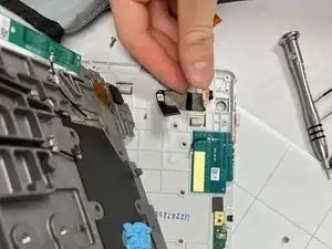
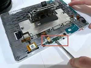
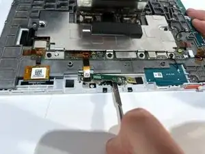
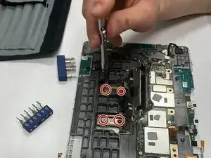
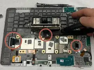
    • Use a spudger to pry under the microphone board. and gently wear away at the connecting glue.

    • The board is glued on so use the spudger to release the glue. It may take some time but be patient to avoid damaging the device.

    • The microphone component is delicate and relatively flimsy, so a gentle approach to breaking the adhesive is recommended.

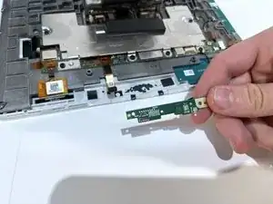
    • After the adhesive seal has been broken, gently lift and remove the microphone board.

  7. Qhw3p3YfTqDfAeHa
    • Remove the eight 7.84 mm black screws from the silver panel using a T5 bit.

  8. OxUpyO2JDmEdHHiM
    • Remove the four 7.73 mm mounting screws from the clip using a T10 bit

  9. YlFDdZirR1XY1OGm
    • Remove the three 3.9 mm silver screws from the board using a T5 bit.

  10. fsdZRY1V2otlgYbZ
    • Remove the seventeen 5.57 mm silver screws using a T5 bit.

  11. aRPKQs1xNP3v4WZZ
    • Carefully disconnect the ribbon cables.

  12. JVv44XO3ExahTOSR
    • Remove the three gold screws (6.9 mm) using a T5 bit screwdriver.

  13. 3DULEl2sFKGLw6aZ
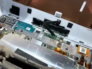
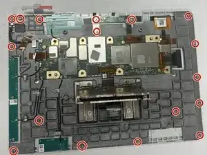
    • Remove the gray backing layer and any loose PCBs (printed circuit boards). You now have access to the camera.

Conclusion

To reassemble your device, reverse the steps outlined in this guide.

Justin Abney

Member since: 01/04/24

154 Reputation

0 comments