Introduction
If your case sustains damage from dropping, spilling stainable substances, or hungry dogs, it's in your best interest to replace it to maintain its clean appearance. This comprehensive guide will lead you step-by-step through the disassembly and replacement process of the outer shell for your Echo Dot.
For this guide, you will need plastic and metal prying tools, and a screwdriver with Torx T4, 6, and 8 heads. This guide has some fragile components, so be careful with the disassembly.
-
-
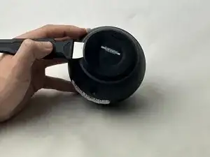
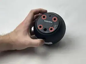
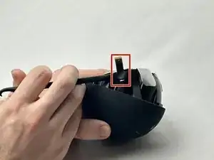
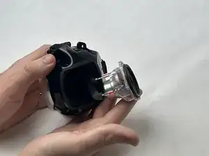
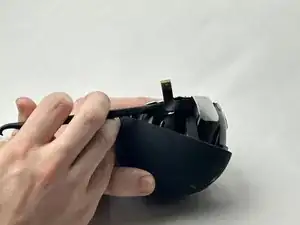
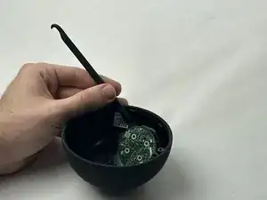
Using a spudger, remove the rubber footing around the base of the Echo Dot. This will reveal the four T8 1.25 cm Torx screws.
-
-
-
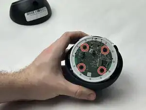
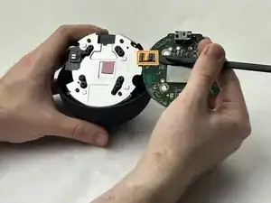
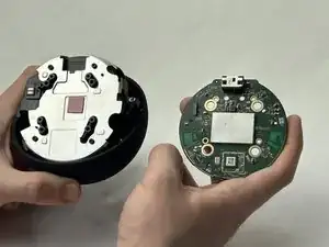
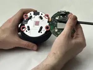
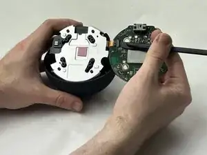
Remove the CPU PCB by removing the 4 T6 0.75cm Torx screws.
-
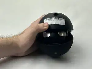
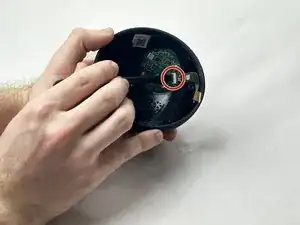
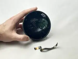
Once removed, unclip the plastic retainer on the CPU PCB and slide the ribbon cable out. This will reveal the speaker’s metal housing.
-
-
-
To access the speaker, take a plastic spudger and slowly lift the ribbon off of the housing.
-
Remove the four T8 1cm Torx screws around the edges of the metal housing.
-
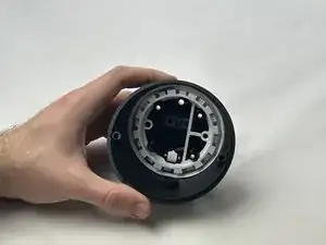
Lift the top case off of the housing to reveal the speaker.
-
-
-
Using a Torx T5 bit, remove the four 1cm screws around the speaker and slide it out of the housing.
-
Pull 2 speaker cables off of the speaker and detach it.
-
-
-
Using the Torx T8 bit, remove the four 1.25 cm screws around the edges of the speaker housing, and lift the housing off of the top case, revealing the switch PCB.
-
-
-
Use a plastic spudger to undo the adhesive attaching the ribbon cable to the top case. Then, flip the tab on the switch PCB, and slide out the ribbon cable.
-
-
-
Remove the upper switch PCB using the T4 Torx bit to unscrew the four 5 mm screws.
-
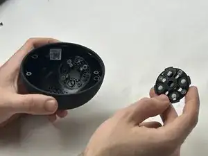
Push down on the buttons through the top of the case and pry lightly with plastic tools until loose, then remove.
-
-
-
By following the previous guides, the device should now be split in two, with the upper switch PCB removed from the top case.
-
Swap the old switch PCB into the new top case, and reassemble.
-

To reassemble your device, follow these instructions in reverse order.