Introduction
How to rebuild an Alber e-motion M15 battery that has suffered the very common failure to charge. This happens due to a failure of a cell or even more commonly due to the cells dropping below the cut off voltage. At this point there's no recovering them and you're at the mercy of a company that charges hundreds for a few nuts and bolts, let alone a few cells.
I could find zero information for rebuilding what is otherwise a $700+ per wheel replacement for a battery that can very easily go under voltage due its lack of battery management and only one Polish company willing to rebuild them. Hopefully even if you don't feel able to rebuild the battery yourself, you can send a link to someone who will see it's not a job they should worry about taking on.
Please forgive the fairly limited photographs, they were to remind me of layouts at the time but I'll try my best to make it into a guide. Please forgive its failings but hopefully it will save somebody some money. Maybe it will also be enough to convince some of the wheelchair battery rebuilders to actually touch these as they're very simple rebuilds for them.
When I tear down the other battery in the future I will provide more photographs.
Please do not attempt to work with li-ion batteries unless you know what you are doing with li-ion batteries.
Tools
Parts
-
-
First you must remove the four circlips holding in the four plastic locking pegs. Pliers, as little bending as you can get away with, and waggling are your friend, you'll need to reuse them.
-
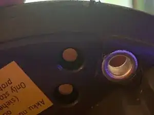
There are now four hollow through rivets that need to be dealt with. If you're lucky you can crunch the back side of these with pliers without having to tear off the padding foam around. If it's a struggle, remove the foam around, slide a spudger or razorblade underneath one side and you should be able to lift enough to squash them.
-
Remove the foam very gently, starting at one of the ends and working your way along the rim. It's not the end of the world if it tears but it's best if you can get it off in one piece without stretching and tearing it. You can try warming it a little with a gentle heat from a hairdryer if it's being stubborn but it should come off fairly easily.
-
Place foam to one side, it should be reusable without any extra adhesive.
-
With the rivets removed you should be able to slide a spudger into the rim of the lid and work it under and pop it off. There's no catches, just a uniform lip all around underneath. Be careful removing it because of the charging cable.
-
-
-
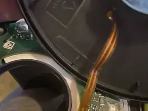
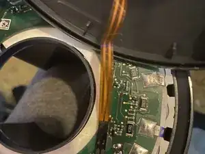
Pull gently holding the black part to remove the charging cable and put the lid to one side. Note the orientation (track side up) and the way it folds.
-
-
-
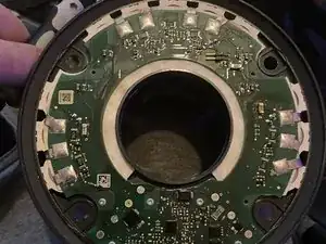
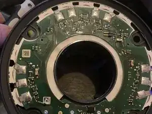
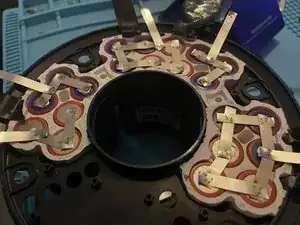
Desolder the battery tabs and mask them off with electrical tape. You will need to use a fairly large soldering iron tip due to the side of the pads. You may well find you need to use an (ideally non-conductive) tool to lift the tabs clear.
-
Once all the tabs are clear, masked, remove all the phillips head screws from the board (several of which I have managed to lose by the time the photograph was taken).
-
Carefully begin lifting the circuit board and the adhesive paper underneath as evenly as possible from all sides. Waggle it a little to begin to loosen it but not too much.
-
Take care whilst lifting as there are three thermistors going down amongst the cells from the board. and you do not want to damage them.
-
When the board is free, place it to one side.
-
-
-
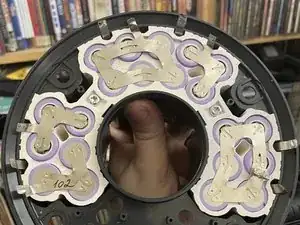
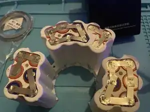
Take multiple pictures of your existing cell layout as you will need to recreate it exactly. (Unfortunately I had clipped one tab on the bottom right before I took the photo).
-
Pry off the old tabs (only if you know what you're doing. The risk of fire and explosion if you do not is very high. It's fully possible to learn but this guide is not where to do it.)
-
Unscrew the two security screws and place battery upside down. There are holes in the back of the pack you can poke a blunt tool into to help push the rubber cell holder out but try to only push on the ones with all or mostly white rubber visible.
-
Eventually you'll be able to remove the white cell holder.
-
-
-
Now is the best chance to take an indellible marker and write the polarity of every cell on the rubber of the holder.
-
Pry off remaining tabs. Maintain all safety precautions.
-
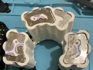
Cells will push out from bottom of holder. (The missing one was found in my coffee).
-
The cells inside were Model: LGEAMF11865 (ICR18650MF1). Capacity: 2150mAh Rated. Voltage: 3.65V Nominal. Charging: 4.20V Maximum 1075mA Standard
-
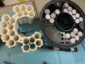
I chose to replace with: Manufacturer: Sanyo/Panasonic · Model: NCR18650GA · Size: 18650 · Capacity: 3500mAh · Maximum Discharge: 10A
-
Make sure to balance the cells by pre-charging them all. You require 21 so you be prepared to do it in advance.
-
-
-
Using a battery spot welder and at least 0.15mm pure nickel strips, recreate the original structure of the pack. (And do a better job than me... although in my defence I did clean up and reweld some of the tabs after this photo was taken.)
-
Complete the underside first, then place it into the battery tub. Remember to take care with the tabs that come off the bottom and secure them with kapton or electrical tape before placing it into the tub.
-
Please only attempt this if you know what you're doing and have practiced. If you have even the slightest doubts please seek advice/help.
-
Once you have completed the welds, replace the circuit board and its paper, taking care to line up the thermistors with the holes in the cell holder.
-
Put fresh solder on the the pads on the board then solder the battery tabs down on their corresponding pads. It may help to hold the pads down with a small screwdriver (taking great care not to touch another pad), then once the solder cools enough to hold the tab, heating the screwdriver tip with the soldering iron enough to remove it).
-
-
-
Reconnect the battery connector track side up.
-
Put lid back on battery, being careful not to trap the cable. Push closed all around.
-
At this point you can carefully test the battery. The battery bolts will be annoying to lock in place without the rivets to guide them but it is possible.
-
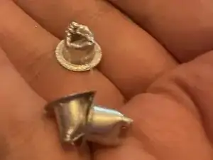
Now the fun part... I never managed to find replacement rivets. If you can find 12mm(head)x8mm(outer)x7mm(inner)x10mm(long although you can cut down anything longer) rivets... you can use them.
-
If you can't... And because the rivets also act to guide the retaining bolts so make life a lot easier...
-
You do what I did and get 8mm copper/aluminium pipe with an inner wall of less than 0.5mm or (I used 0.25mm because it was half the price.
-
I then used a mini pipe cutter to cut approx 14mm lengths, used side cutters to cut a few 2-3mm cuts at each end, put it through the holes, and then bent those back like petals to make crude rivets.
-
Put the bolts back through the holes, put the circlips back on, bend the circlips so they retain the bolts again.
-