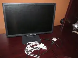
Introduction
If your AL2216W is having problems, it is likely due to bad capacitors. Here are some common symptoms of bad capacitors:
Note: While some issues may be corrected with a partial repair, this is NOT RECOMMENDED. One bad capacitor usually means the rest will fail!
- Power issues (Present issue)
- Excessive transformer/inverter hum (Present)
- Backlight problems
- Auto adjust problems (VGA) (Present)
- Random power issues that only resolve if the monitor is unplugged
- Video issues (Ex: Unstable image, video instability)
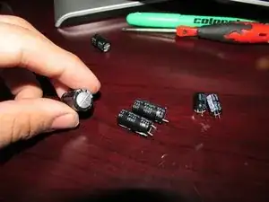
Original capacitor values (For Delta 00A power supply)
NOTE: I based the capacitor list on my monitor's specific power supply (Delta 00A). AS SUCH, YOURS MAY BE DIFFERENT. TO AVOID ISSUES WITH PARTS COMPATIBILITY, YOU MUST OPEN THE MONITOR UP TO VERIFY WHAT SPECIFIC CAPACITORS ARE USED. In addition to this, almost all of the original specced parts for the Delta 00A power supply are NLA or hard to come by and may need to be substituted with a part that has a higher voltage (V) or a higher microfarad rating (uF). If it comes down to this you must replace the entire bank of the substituted part otherwise the other capacitors are very likely to fail if they get power from the upgraded capacitor and are overloaded. This is the only real "issue" you may run into when upgrading parts; there are no issues in doing so otherwise as long as the upgrade is reasonable (Ex: 25v 1000uF no longer available, 35v 1000uf available).
NOTE: I have not attempted partial capacitor replacements with upgrades, so I do not know how keeping the originals and upgraded capacitors will affect the board. Even then, this is terrible practice; one going out usually means the others are next.
Part availability caution: While I did my best throughout this guide's life to keep up with part phaseouts (and "obsolete in practice" parts) by mitigating this issue with parts that are similar in voltage or uF, I cannot continuously monitor the market. You may need to make a substitution I did not make!
- 25V 1000uF (x2)
- 10V 1000uF (x1)
- 25V 220uF (x2)
- 16V 2200uF (x1, Found on early power supplies and is used to drive the inverter transformer. Not used on most power supply revisions as it was later removed)
-
-
Remove the 4 screws from the monitor stand with a Philips #1 screwdriver. Remove the bottom screws first.
-
-
-
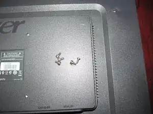
Sort this screw separately, as it is unique.
-
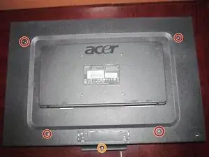
Remove 4 fine threaded screws from the back of the monitor with a Phillips #0 screwdriver. All of these screws are the same.
-
-
-
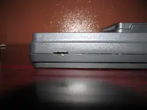
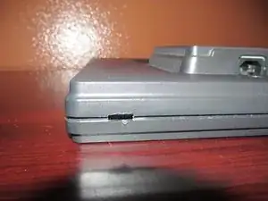
On the bottom of the monitor, there are four slots to open the monitor. To release these clips, use a Jimmy or flathead screwdriver.
-
-
-
With the monitor unclipped on the bottom, pull the sides of the monitor up. Do this slowly to avoid cracking the LCD.
-
-
-
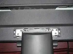
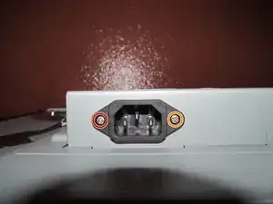
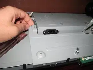
With the back of the monitor off, remove the 2 screws on the IEC power connector using a Phillips #0 screwdriver.
-
-
-
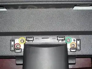
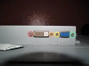
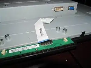
Remove the 4 screw pins for the video cables from the monitor. Use a 5mm Nut bit/driver to remove the screw pins from the power supply shield.
-
-
-
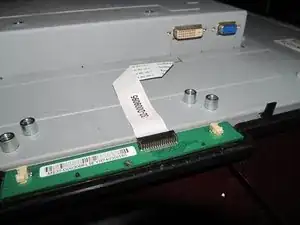
Remove the 2 lower screws that hold the power supply shield to the monitor with a Phillips #0 screwdriver.
-
-
-
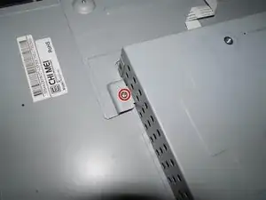
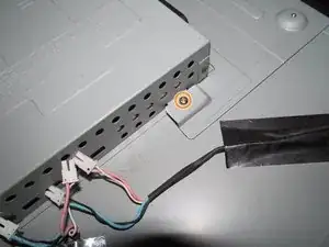
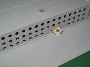
On the right side of the monitor, remove the remaining screws holding the shield in place.
-
Lift the lower plate up while removing the power supply shield to remove it from the monitor. Once this is done, you will have access to the power supply.
-
-
-
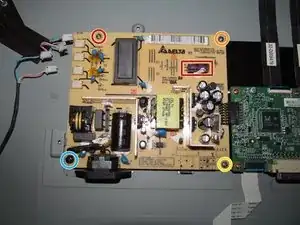
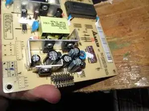
This capacitor is only found on older power supplies. Replacement is advised, but not required.
-
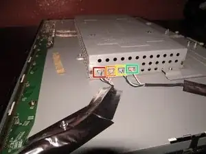
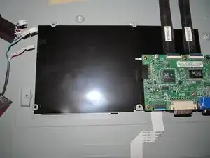
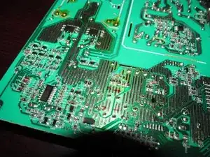
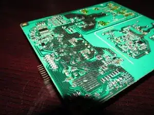
With the power supply shield removed from the monitor, identify the power supply. Take note of the values, including the inverter cap (if present).
-
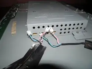
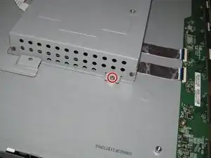
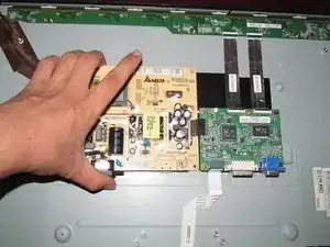
Remove the 4 screws from the power supply. Once this is done, lift up the power supply at a slight angle to clear the chassis. Do not lift too much or the connector may be damaged!
-
-
-
If you are unsure of the position of the capacitors, mark the polarity with a permanent marker. If the capacitors are incorrectly installed, they will explode when power is applied.
-
-
-
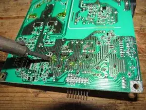
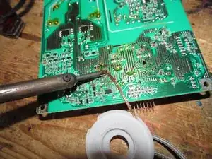
Move to a workspace with ventilation or use a fume extractor. Once in an appropriate workspace, desolder the old capacitors. Heat up each leg and remove it.
-
After removing the capacitors, clean up the old solder with a desoldering braid. Lift it with the iron when removing it.
-
-
-
Install the new capacitors. Check the polarity and bend the leads so they do not come loose during installation.
-
-
-
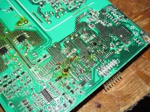
Once the polarity is verified, solder the capacitors in. After installation, cut off any excess lead.
-
-
-
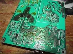
After verifying there are no cold solder joints, clean the board. This can be cleaned with 91%+ Isopropyl or denatured alcohol.
-


To reassemble your device, follow these instructions in reverse order.

28 comments
I did not replace the large capacitor on the Acer monitor yet. All other caps have been replaced. I may have to replace the FSPO55- ZP102A as it has a hot spot beside it. I don't know if the part number is right? Do know where I can buy it. Tom B
These older CCFL panels usually burn on the PCB by the inverter coil and main transformer (the Delta branded part, in this case). The LED monitors limit the failure points to the transformer.
It sounds like your PCB got burned from the heat by the transformer or the inverter coil. This is very common and the boards are designed to take it. However, if you are concerned you should buy a new power supply board altogether if that makes you more comfortable.
Nick -
In step 12, replacing the capacitors with ones with a different capacitance rating instead of using a capacitor rated for higher voltage makes no sense to me electrically. The capacitance rating is the important part, if you use a capacator rated for say 35 volts when the original is rated for 10 makes no difference whatsoever. the rating just means MAX voltage.
The big one on the AC side.
Nick -
It’s okay to use the matched and upgraded caps at the same time. The ones I upgraded were hard to find since they’re more or less obsolete.
Nick -
Ok thanks! reason why is I got all my replacements scrapping dead Power supplies. so I managed to get some and some others
Aiden -
That’s a way to get extra groundplane with minimal cost. By design, it gets covered in solder during assembly. I wouldn’t leave solder on those.
Nick -
also one more thing. which capacitors do the upgraded ones replace?
Aiden -
Yeah. It’s a bad idea to bridge it. The places the upgraded caps go are listed in the part descriptions as a note if it was replaced.
Nick -
OK. I didn’t expect to find the monitor I needed to replace on ifixit out of tons of others that are not. thanks for making the guide!
Aiden -
Most of the monitors people usually buy are low end and are rarely worth repairing or the owner is too lazy to bother because of how cheap a good one is today. I only ever see good monitors like Dell Ultrasharps in use by businesses.
On one hand it’s a waste but if I can get it and fix it for relatively little money I’ll try.
Nick -
The capacitor by the coil. Some revisions don’t have it.
Nick -
the one in step 12?
Aiden -
The one with the red box around it.
Nick -
@captainsnowball And I figured out what the issue may have been almost 4 years later :-(. I assumed the Delta 00A supply was the common unit and common sense would dictate the information on the caps I have is specific to the 00A part, but that wasn’t the case.
It’s been fixed for a while, but the issue has been ongoing for a long time because it’s been patched to help rather then properly fixed. I’m going to keep it for cases like yours where you need a starting point, but it had to be clarified. The monitor really needs to come apart to be sure, so I may remove it as it isn’t definite and may vary.
Nick -